Beam splitting device, system, method and application

A distribution method and beam current technology, applied in the directions of accelerators, electrical components, etc., can solve the problems of ineffective beam splitting and single beam cluster screening, and achieve the effects of beam splitting stability, cavity frequency stability, and space size reduction.

Active Publication Date: 2021-11-26
INST OF MODERN PHYSICS CHINESE ACADEMY OF SCI
View PDF3 Cites 0 Cited by
  • Summary
  • Abstract
  • Description
  • Claims
  • Application Information

AI Technical Summary

Problems solved by technology

[0004] In view of the above technical problems, the present invention provides a beam splitting device, system, method and application. The device uses a fast beam splitting device to divide the intense current beam generated by the accelerator according to the needs of different physical experiments or industrial applications. , extract the beam at different energies, and modulate it into different time structures and spatial distributions, and provide beams to multiple different application terminals at the same time, which solves the problem that the existing technology cannot control the beam interval in nanoseconds in a compact space The problem of effective beam splitting and single-bundle screening of large-scale high repetition rate, high energy, and strong current beams

Method used


Image

  • Beam splitting device, system, method and application
  • Beam splitting device, system, method and application
  • Beam splitting device, system, method and application

Examples


Embodiment 1

[0043] This embodiment provides a beam splitting device, and its structure will be described in detail below.

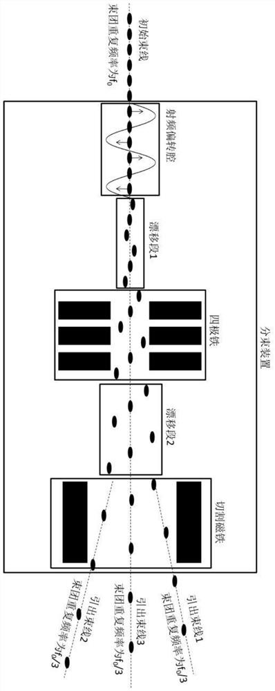
[0044] refer to figure 1 , the beam splitting device includes: a radio frequency resonant cavity; a drift section 1; a quadrupole iron; a drift section 2 and a cutting magnet, and these components are connected in series in sequence.

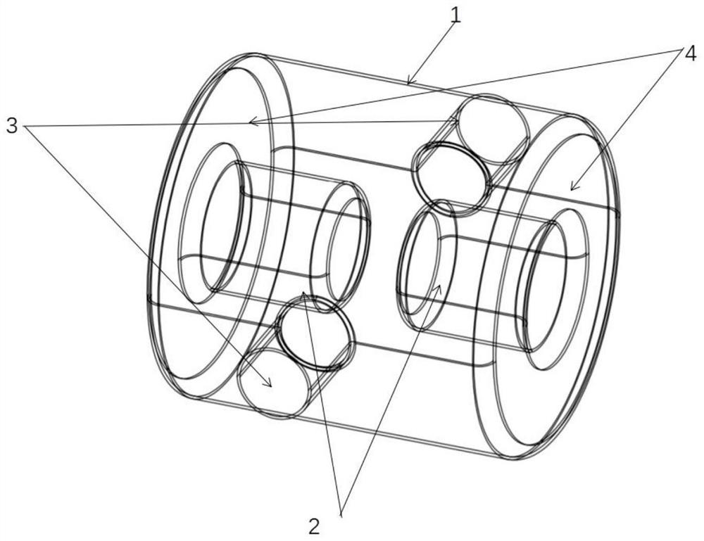
[0045] The radio frequency deflection cavity adopts a double quarter wavelength cavity structure, which is composed of an outer conductor 1 , an inner conductor 2 , an end cover 4 and a beam pipe 3 . Under the same cavity frequency, the size of the double quarter-wave cavity is smaller, which can effectively reduce the space size of the entire beam splitting device; its shunt impedance is higher, and it can give the cavity passing through the cavity at the same cavity loss. The beam current provides greater lateral momentum, thereby shortening the longitudinal length of the entire beam splitting device; and its inner and outer conduct...

Embodiment 2

[0055] Embodiment 2 provides a beam distribution method, using the beam splitting device provided in Embodiment 1, the method includes the following steps:

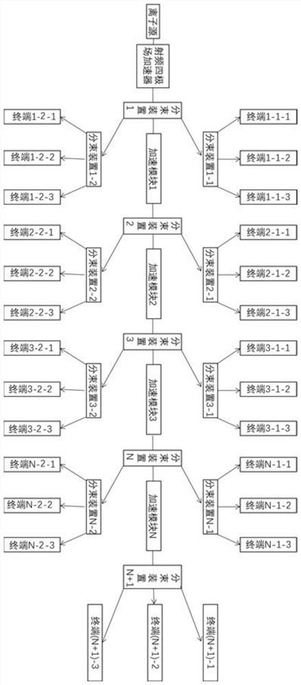
[0056] Step A: The beam current generated from the ion source is modulated into micro-bunches one by one after passing through the radio frequency quadrupole field accelerator, and these micro-bunches enter the acceleration module or deceleration module (acceleration module or deceleration module 1, acceleration module or The deceleration modules 2, . . . , the acceleration modules or the deceleration modules N) are subjected to step-by-step acceleration. After each acceleration module or deceleration module there are beam splitters (beam splitter 1, beam splitter 2, ... beam splitter (N+1)) and secondary beam splitters (beam splitter 1-1 , beam splitting device 1-2, ... beam splitting device N-2), realize multiple different terminals (terminal 1-1-1, terminal 1-1-2, ... terminal (N+1)-3 ) at the same time for beam. The...

Embodiment 3

[0062] Embodiment 3 provides an application of a beam distribution method, using the beam distribution method provided in Embodiment 2, the application includes some content:


PUM


Abstract

The invention relates to a beam splitting device, system, method and application. The beam splitting device comprises a radio frequency deflection cavity, a first beam pipeline (drifting section 1), quadrupole iron, a second beam pipeline (drifting section 2) and a cutting magnet which are sequentially connected in series; the radio frequency deflection cavity comprises an outer conductor and an inner conductor, the outer conductor is provided with a beam channel, the inner conductor is used for applying a transverse electric field and a transverse magnetic field to the beam flowing out of the beam channel so as to generate transverse momentum, and the outer conductor and the inner conductor are connected through an end cover. The device provided by the invention can perform beam splitting on the high-current beam at the ns-level time interval, and provides beams for a plurality of different application terminals at the same time, so the utilization efficiency of the high-current beam is improved.

Description

technical field [0001] The present invention relates to a beam splitting device, system, method and application, in particular to a fast beam splitting device, a beam splitting system, a beam distribution method and an application for improving the utilization efficiency of high-current beams, belonging to particle Accelerator beam modulation technology field. Background technique [0002] Particle accelerators can generate high-energy and high-current particle beams for a series of industrial applications such as scientific physics experimental research and isotope production, nuclear pore membrane manufacturing, material irradiation, neutron sources, muon beam generation, and particle cancer treatment. Different experimental terminals or application terminals have different requirements on the current intensity, pulse length, repetition frequency and energy of the beam. With the development of high-power high-current particle accelerators, the beam intensity that particle...

Claims


Application Information

Patent Timeline
Patent Type & Authority Applications(China)
IPC IPC(8): H05H7/00
CPCH05H7/001H05H2007/002H05H2007/004
Inventor 黄玉璐贾欢秦元帅何源张周礼王志军
Owner INST OF MODERN PHYSICS CHINESE ACADEMY OF SCI
Why Eureka
Try Eureka