Element absorption method and device

An adsorption device and adsorption position technology, which is applied to electrical components, electrical components, conveyor objects, etc., to achieve the effects of shortening the adsorption cycle, accurate correction, and reducing the number of recognitions

Inactive Publication Date: 2010-07-14
JUKI CORP
View PDF3 Cites 0 Cited by
  • Summary
  • Abstract
  • Description
  • Claims
  • Application Information

AI Technical Summary

Problems solved by technology

[0006] However, in the conventional method of obtaining the coordinates of the suction position of each component, it is necessary to identify the components stored on the storage tray one by one, so there is a problem that the suction cycle increases. question

Method used


Image

  • Element absorption method and device
  • Element absorption method and device
  • Element absorption method and device

Examples


Embodiment Construction

[0021] Hereinafter, the present invention will be specifically described based on illustrated examples.

[0022] (Example)

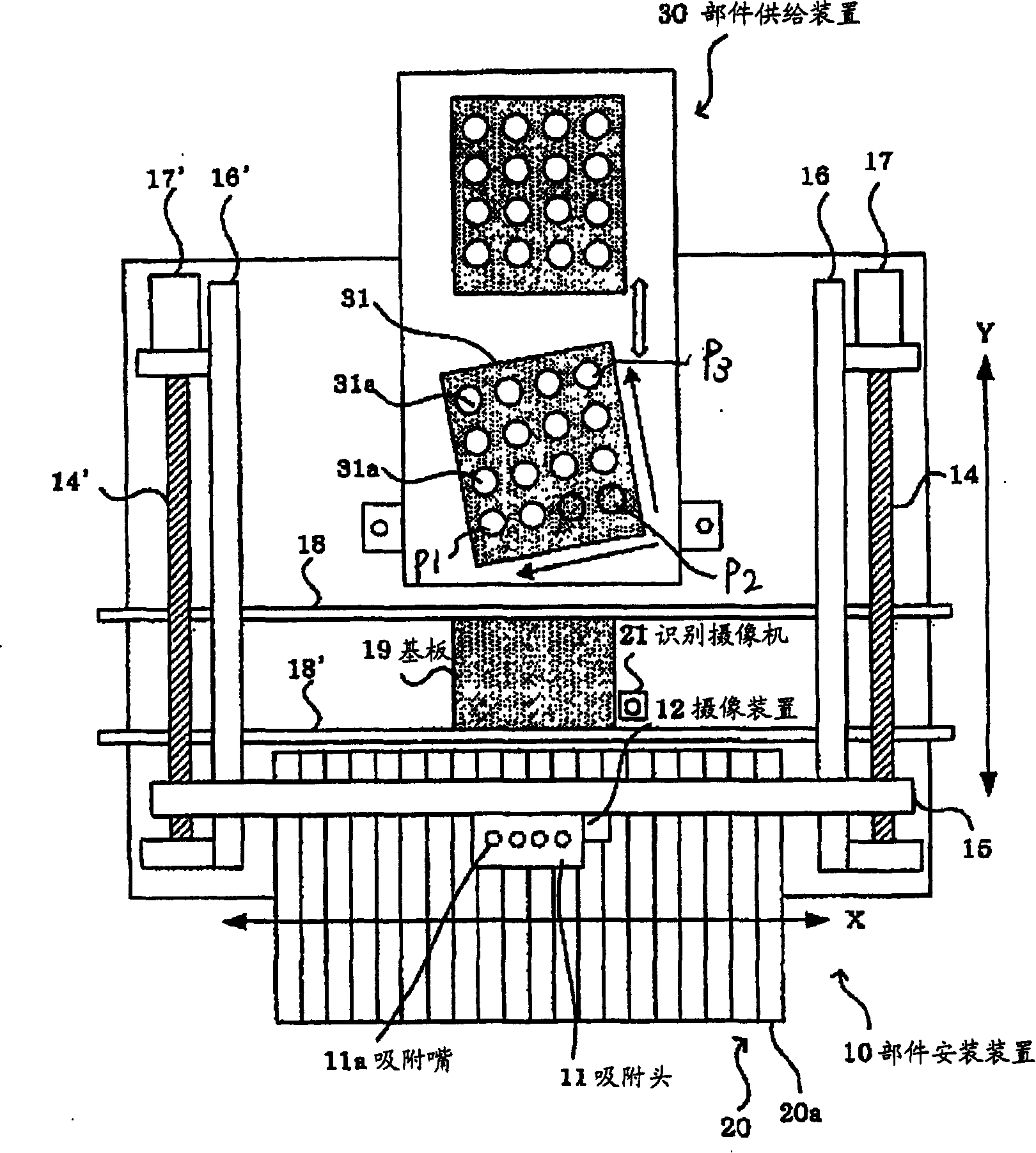
[0023] exist figure 1 The component mounting device 10 is shown in , and the suction head 11 is provided in the component mounting device 10 , which can move in the X-axis direction along the X-axis guide rail 15 by an X-axis motor (not shown). The X-axis guide rail 15 is combined with the screw shaft 14, 14', and the screw shaft is rotated by the Y-axis motor 17, 17', thereby moving in the Y-axis direction along the Y-axis guide rail 16, 16'.

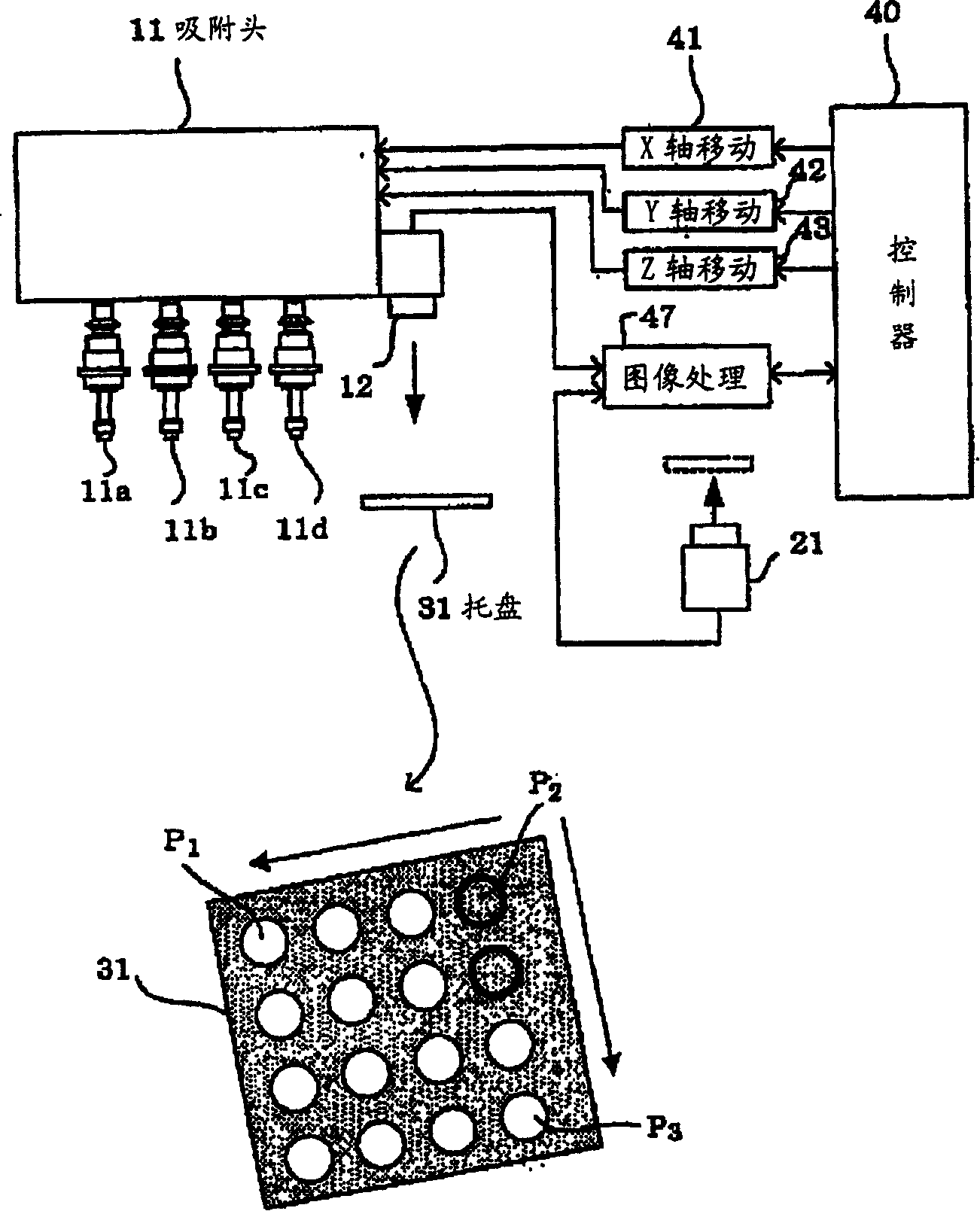
[0024] exist figure 2 Among them, the X-axis moving means such as the X-axis motor and the X-axis guide rail 15 are represented by the reference numeral 41, and the Y-axis movement means such as the Y-axis motor 17, 17', the screw shaft 14, 14', the Y-axis guide rail 16, 16', etc. are represented by the reference numeral 42. Axis movement means. The controller 40 of the component mounting apparatus moves th...


PUM


Abstract

The present invention provided a parts adsorbing method of adsorbing parts stored in a parts storage tray in a simple and correct manner and in a short period of time, and to provide a parts adsorbing device. According to the parts adsorbing method, the parts stored in the storage tray 31 which has been moved to a parts feeding location, are adsorbed by an adsorbing head 11. An image pickup device 12 mounted on the adsorbing head is moved to predetermined parts storage locations P1, P2, P3 in the storage tray, and images of the parts stored in the storage tray or parts storage portions are picked up, to thereby obtain a correction value of each of the parts adsorbing location, based on a result of image processing. According to the method, a correction value at a location other than the selected locations P1, P2, P3 can be obtained by linear interpolation, for instance, and therefore individual storage portions are need not be recognized, which leads to drastic reduction in the numberof times of recognition as a whole, to thereby reduce an adsorbing tact.

Description

technical field [0001] The present invention relates to a component suction method and device for sucking and storing components on a storage tray moved to a component supply position by using a suction head in a component mounting machine. Background technique [0002] Conventionally, there is known a component mounting apparatus that uses suction nozzles of a suction head to suction electronic components (hereinafter, simply referred to as components) on a storage tray containing a plurality of components, and mounts the suctioned components on a conveyed circuit board. at the predetermined position. [0003] When the tray supply device is used, the storage tray is moved from the tray supply device to the component supply position of the component mounting device, and the suction head of the component mounting device absorbs the components stored in the storage tray. At this time, if the storage tray is not accurately positioned, the indicated component cannot be sucked,...

Claims


Application Information

Patent Timeline
Patent Type & Authority Patents(China)
IPC IPC(8): H05K13/02B65G47/91
Inventor 栗田直树
Owner JUKI CORP
Why Eureka
Try Eureka