Labeling apparatus

A labeling and labeling technology, which is applied in the direction of labels, labeling machines, laminating devices, etc., can solve problems such as the inability to adjust the advance travel of the bearing width, and achieve the effect of improving reliability and accuracy

Inactive Publication Date: 2007-01-10
CHECKPOINT SYST INC
View PDF1 Cites 1 Cited by
  • Summary
  • Abstract
  • Description
  • Claims
  • Application Information

AI Technical Summary

Problems solved by technology

In addition, the disadvantage often arises that the use of corundum pads as clamping elements does not allow adjustme

Method used


Image

  • Labeling apparatus
  • Labeling apparatus
  • Labeling apparatus

Examples


Embodiment Construction

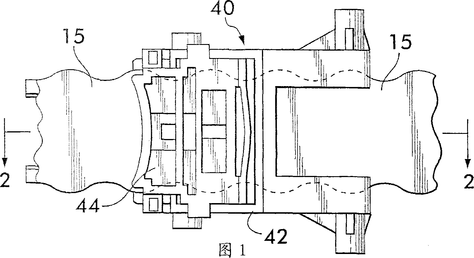
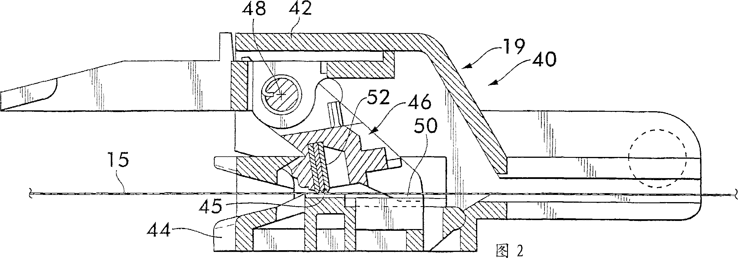
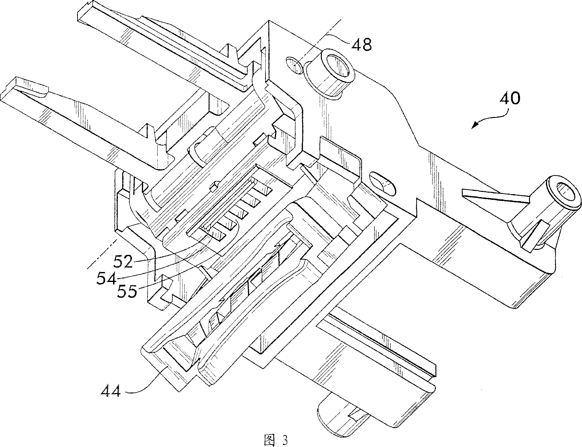
[0022] Except for the structure of the feeding mechanism 19, the manufacturing method of the labeling device of the present invention is the same as that shown in FIG. 6 . Therefore, to avoid repetition, Figures 1 through Figure 5 Only the transfer carriage 40 and its detailed transfer pawls, which are part of the feed mechanism 19 of the labeling device according to the invention, are illustrated. In more detail describe Figures 1 to Figure 5 Previously, the operation of the known labeling device will be described with reference to FIGS. 6 and 7 .

[0023] The labeling device shown in Figure 6 has a housing 11 on which a handle 12 is integrally formed. A compartment 13 is provided on the upper side of the housing to accommodate a supply reel 14 for a carrier web 15 to which self-adhesive labels 16 are glued. The carrier web 15 extends in the labeling device from the supply reel 14 in the compartment 13 to the bottom left as shown in FIG. This deflection extends to the r...


PUM


Abstract

The invention is directed to a labeling apparatus for dispensing and applying self-adhesive labels arranged on a carrier web (15) adapted to be fed step-by-step. By means of a lever mounted for pivotal movement on a housing of the labeling apparatus a feeding mechanism (19) for the carrier web is adapted to be driven. The feeding mechanism (19) includes a transport slide (40) with a transport pawl (46) and a table (45). On each pivoting cycle of the lever the carrier web (15) is adapted to be held clamped between a clamping member (52) of the transport pawl (46) and the table (45) for entrainment by the transport slide (40). The clamping member (52) includes several cutting edges (52a-52c) arranged adjacent to each other in the feed direction, hence enabling line contact to be established between the clamping member (52) and the carrier web (15) in a direction transverse to the feed direction of the carrier web. By virtue of the line contact between the clamping member (52) and the carrier web (15), service life, reliability and accuracy of the feeding mechanism (19) are improved.

Description

technical field [0001] The present invention relates to a labeling apparatus for dispensing and applying self-adhesive labels arranged on a carrier web adapted to be progressively fed, said The labeling device has a lever arranged for a pivotal movement on the housing to drive a feeding mechanism for the carrier web, said feeding mechanism Comprising a transport slide with a transport pawl and a table so that the carrier web fits in a grip of the transport pawl for each cycle of rotation of the lever. The holding member is fixedly clamped between the platen so as to be entrained by the transfer slide. Background technique [0002] Labeling devices of this type are known in many designs in the form of hand-held labeling machines, which are used for price marking in retail stores, especially in supermarkets and self-service vending establishments. [0003] The first mention of a labeling device of this type is from German patent document DE 4309441 A1. The well-known labeli...

Claims


Application Information

Patent Timeline
IPC IPC(8): B65C11/00B65C9/30B32B37/00B65C11/02
CPCB65C11/0263B65C11/0215
Inventor 彼得·本德
Owner CHECKPOINT SYST INC
Why Eureka
Try Eureka