Heating cooker

A technology for heaters and cookers, which is applied to electric heating fuel, containers with enlarged heating surfaces, lighting and heating equipment, etc., and can solve problems such as overheating, inability to use, and inability to measure the temperature of heated objects correctly.

Inactive Publication Date: 2007-01-17
HITACHI APPLIANCES INC
View PDF3 Cites 13 Cited by
  • Summary
  • Abstract
  • Description
  • Claims
  • Application Information

AI Technical Summary

Problems solved by technology

Therefore, the temperature of the object to be heated cannot be measured correctly
As a result, the heating control based on the temperature detection results of the infrared temperature sensor cannot work normally. For example, abnormal situations such as insufficient heating and excessive heating will occur. Going to the next step in a state of poor heating, reheating and natural cooling alone cannot solve the problem, and there is a possibility that cooking will end in failure
[0012] Therefore, in a heating cooker using steam, it is very difficult to accurately measure the temperature of the object to be cooked in the heating chamber with an infrared temperature sensor, and there is a problem that the infrared temperature sensor cannot be used as a heating control device.

Method used


Image

  • Heating cooker
  • Heating cooker
  • Heating cooker

Examples


Embodiment 1

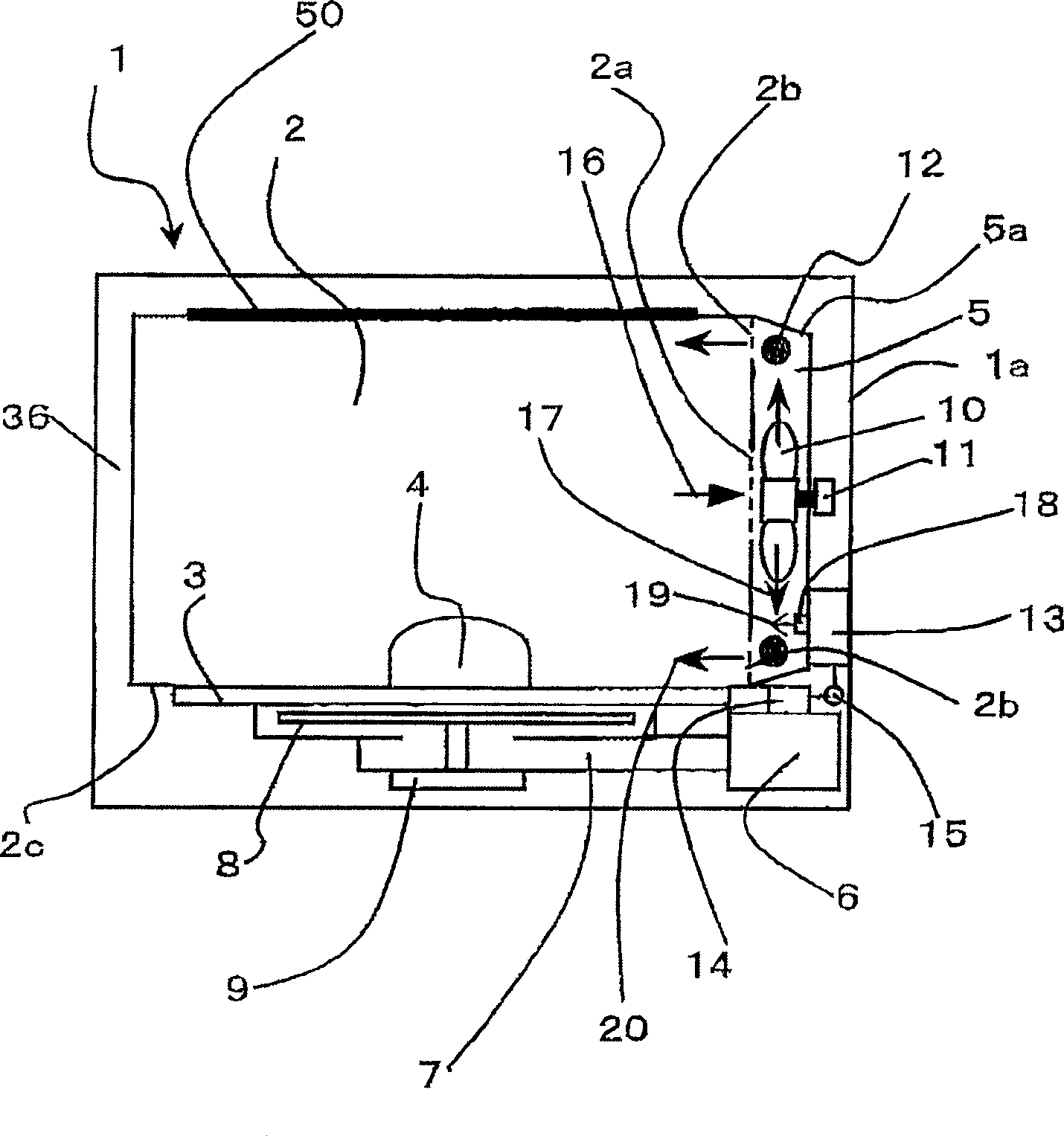
[0035] figure 1 It is a side sectional view of the electric oven cooking range of the present invention.

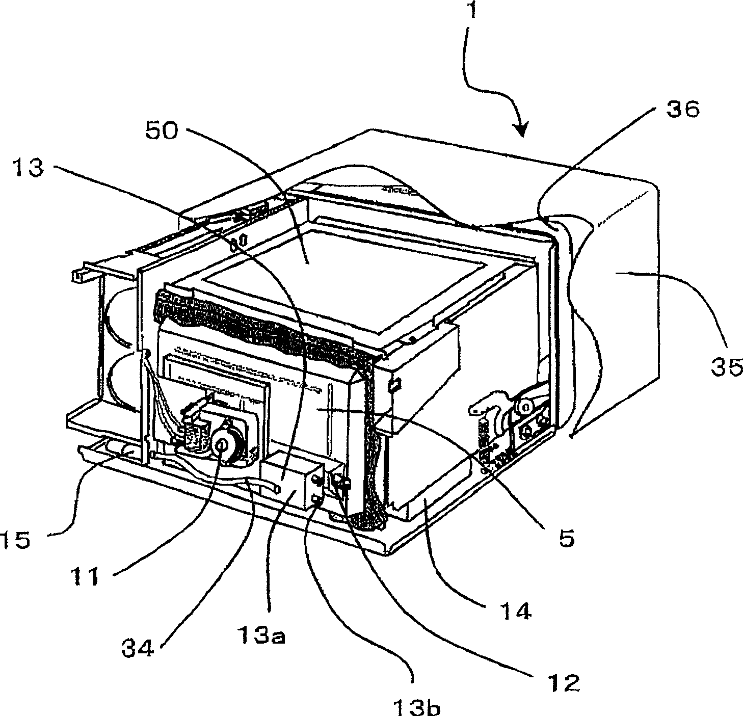
[0036] figure 2 It is a perspective view of this electric oven cooking range as seen from the back side, and it is the state which moved the cover 35 which is an outer frame to the front (door 36 side) of a main body.

[0037] The main body 1 of the electric oven cooking range is composed of the following components: a heating chamber 2 for accommodating food to be cooked 4 such as heated food, and a non-rotating table 3 on the bottom surface 2c of the heating chamber 2 for placing the food 4 , The hot air unit 5 that circulates the hot air in the heating chamber 2, the magnetron 6 as the heating source of the cooking stove heating device, the waveguide 7 that guides microwaves, the rotating antenna 8 and the antenna motor 9 that irradiate the microwave to the heating chamber 2 and so on.

[0038] Since the above-mentioned magnetron 6, wave guide 7, rotating antenna 8 and ...

Embodiment 2

[0074] Figure 4 Is another embodiment of the present invention, and figure 1 It is also a side cross-sectional view of an electric oven cooking range without a turntable. The big difference is that the table 3 placed on the bottom of the heating chamber 2 is separated from the heating chamber 2, and can be freely installed and unloaded from the heating chamber 2. A quality detection device 22 for measuring the weight of the food 4 is installed underneath. Here, although only one first heater 12 is provided near the delivery port 18 of the steam generating device 13 located on the lower side of the hot air unit 5, it may be as figure 1 Shown is divided into two settings, top and bottom.

[0075] Figure 5 It is a perspective view seen from the front side of the cooking range of the electric oven, with the cover as the outer frame removed.

[0076] According to this structure, it is characterized in that the mass detection device 22 detects the weight of the food 4 on the table...

Embodiment 3

[0109] Picture 9 It is another embodiment of the present invention, which is different from the above-mentioned embodiment. It is a side cross-sectional view of a rotary table type electric oven cooking range in which the rotary table 32 on which the object to be cooked 4 is placed in the center of the heating chamber 2 is freely rotatable, The structure is that the microwave generated from the magnetron 6 is irradiated to the object 4 to be cooked from the side of the heating chamber 2 through the waveguide 7.

[0110] The turntable 32 is rotated by a turntable motor 33 located at the lower part of the turntable, and a quality detection device 22 is provided at the end of the same axis. The quality detection device 22 can be used to detect the weight of the food 4 placed on the turntable 32. The quality detection signal 23 is sent to the control device 27. The cooking method is the same as the above description.


PUM


Abstract

The heating cooker provided by the present invention can simultaneously realize rapid moisture retention of the cooked object and various and efficient heating cooking of the cooked object, thereby simply providing delicious cooking. The heating cooker of the present invention has 4 heating devices: the heating device of the cooking stove using the magnetron (6) as the heat source, the hot air made of the first heater (12) and the fan (10) and the ventilation duct (5a) An oven heating device, a grill heating device using the second heater (50) as a heat source and a heating device composed of high-temperature water vapor (20) generated by the steam generator (13) and the first heater (12); The above-mentioned steam generating device is arranged on the outside of the air passage (5a), and the water vapor (19) supplied from the steam generating device is sprayed to the airflow flowing out from the fan, and the mixed water vapor is heated by the first heater to generate high-temperature steam , into the heating chamber (2) for cooking the object to be heated (4).

Description

Technical field [0001] The present invention relates to a heating cooker such as an oven cooking range. Background technique [0002] In the conventional heating cooker, as shown in Patent Document 1-Japanese Patent Laid-Open No. 2005-061816, it has a heating chamber containing the object to be heated, a steam generating device, and a jet hole provided in the upper part of the heating chamber. In addition, the steam generated by the steam generator is ejected from the air jet hole in the upper part of the heating chamber to surround the object to be heated in the heating chamber for cooking. [0003] In addition, as shown in Patent Document 2-Japanese Patent Application Laid-Open No. 2004-309060, there is a heating cooker that supplies heat from a heat source to a heating chamber containing an object to be cooked and heat-treats the object to be heated. A steam generating part that supplies steam in the heating chamber, a heater and water supply device that heats the steam genera...

Claims


Application Information

Patent Timeline
Patent Type & Authority Applications(China)
IPC IPC(8): F24C7/02A47J27/02
Inventor 木村秀行本间满田中佐知堀切泰逸见泰章
Owner HITACHI APPLIANCES INC
Why Eureka
Try Eureka