Heating cooker

A cooker and heating chamber technology, applied in the direction of electric heating fuel, steam cooking utensils, lighting and heating equipment, etc., can solve the problems of overheating, incorrect heating control, and difficulty in correct temperature measurement, etc., to achieve expansion The effect of application range

Inactive Publication Date: 2009-09-02
HITACHI HOME & LIFE SOLUTIONS INC
View PDF6 Cites 0 Cited by
  • Summary
  • Abstract
  • Description
  • Claims
  • Application Information

AI Technical Summary

Problems solved by technology

However, there is a problem that even if the combination of radio wave output and humidity corresponding to the type of food can be stored in the memory, if the amount of food (such as the quality of the food, how many servings) is unknown, it cannot be heated correctly. control
Therefore, the temperature of the object to be heated cannot be accurately measured
Then, the heating control performed according to the temperature detection result of the infrared temperature sensor does not operate normally, resulting in inappropriate situations such as insufficient heating and excessive heating. In the next stage, it cannot be processed by simple reheating or refrigerating, and it may end in cooking failure.
[0018] Therefore, in heating and cooking using steam, it is difficult to accurately measure the temperature of the object to be cooked in the heating chamber with an infrared temperature sensor, and there is a problem that the infrared temperature sensor cannot be used as a device for heating control.

Method used


Image

  • Heating cooker
  • Heating cooker
  • Heating cooker

Examples


Embodiment 2

[0080] Figure 4 is another embodiment of the present invention, although with figure 1 The same is a non-rotary electronic microwave oven, but the stage 3 arranged on the bottom surface of the heating chamber 2 is separated from the heating chamber 2, and can be freely assembled and disassembled with the heating chamber 2. 4. The mass detection device 22 of weight is the biggest difference.

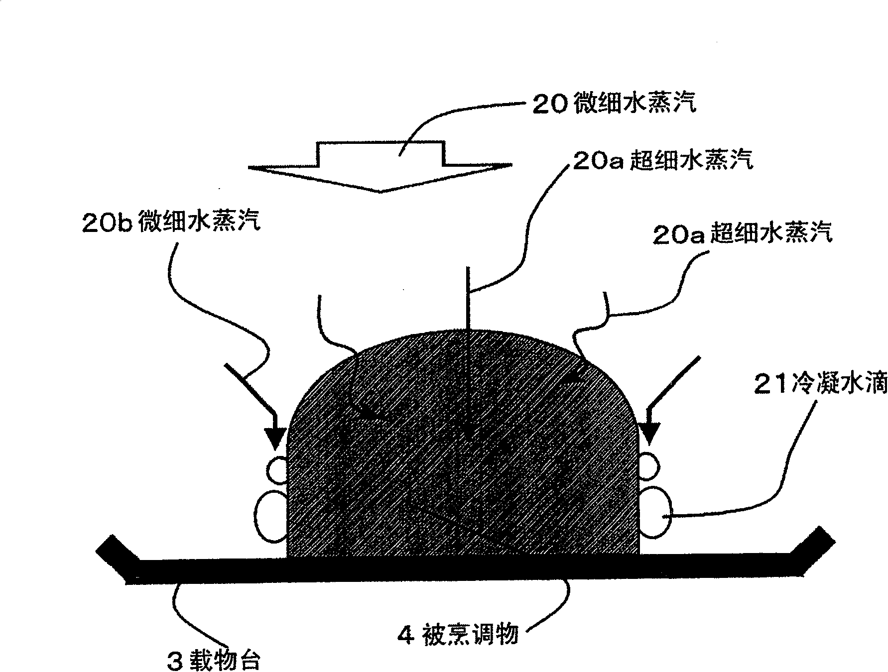
[0081] According to this structure, it is characterized in that the weight of the object to be cooked 4 on the stage 3 can be detected by the quality detection device 22, and the water vapor quantity 19 supplied from the steam generating device 13 is controlled by the control device 27 according to the detected value, And an appropriate amount of fine water vapor 20 corresponding to the cooking content of the object to be cooked 4 is supplied into the heating chamber 2 .

[0082] Figure 5 It is an example of the mass detection device 22, and the measurement principle is a capacitive ...

Embodiment 3

[0111] Figure 8 It is another embodiment of the present invention, which is different from the above-mentioned embodiment. It is a turntable electronic microwave oven in which the rotary stage 32 arranged in the center of the heating chamber 2 rotates. It is the same as the above-mentioned embodiment, and has a hot air unit 5 .

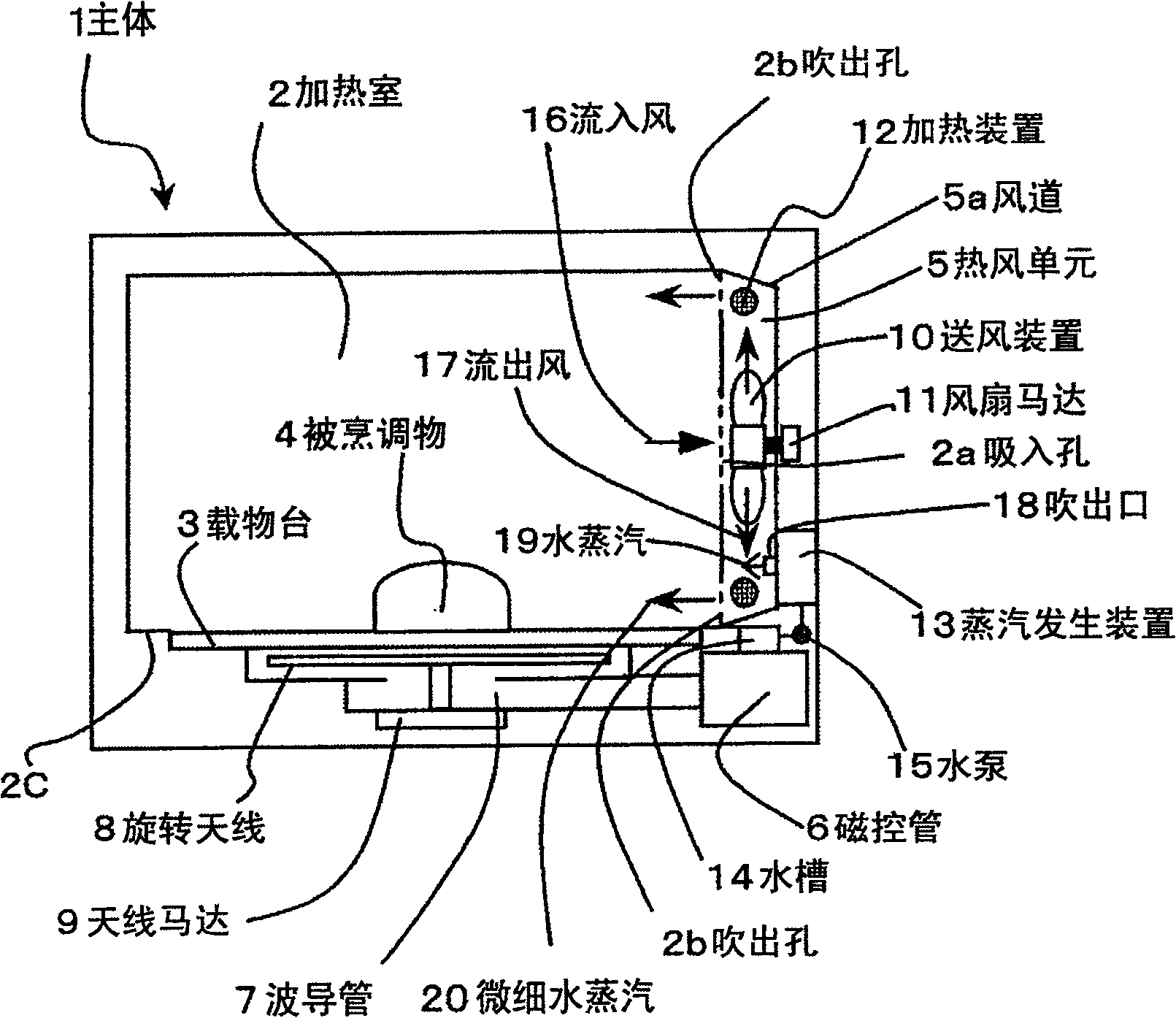
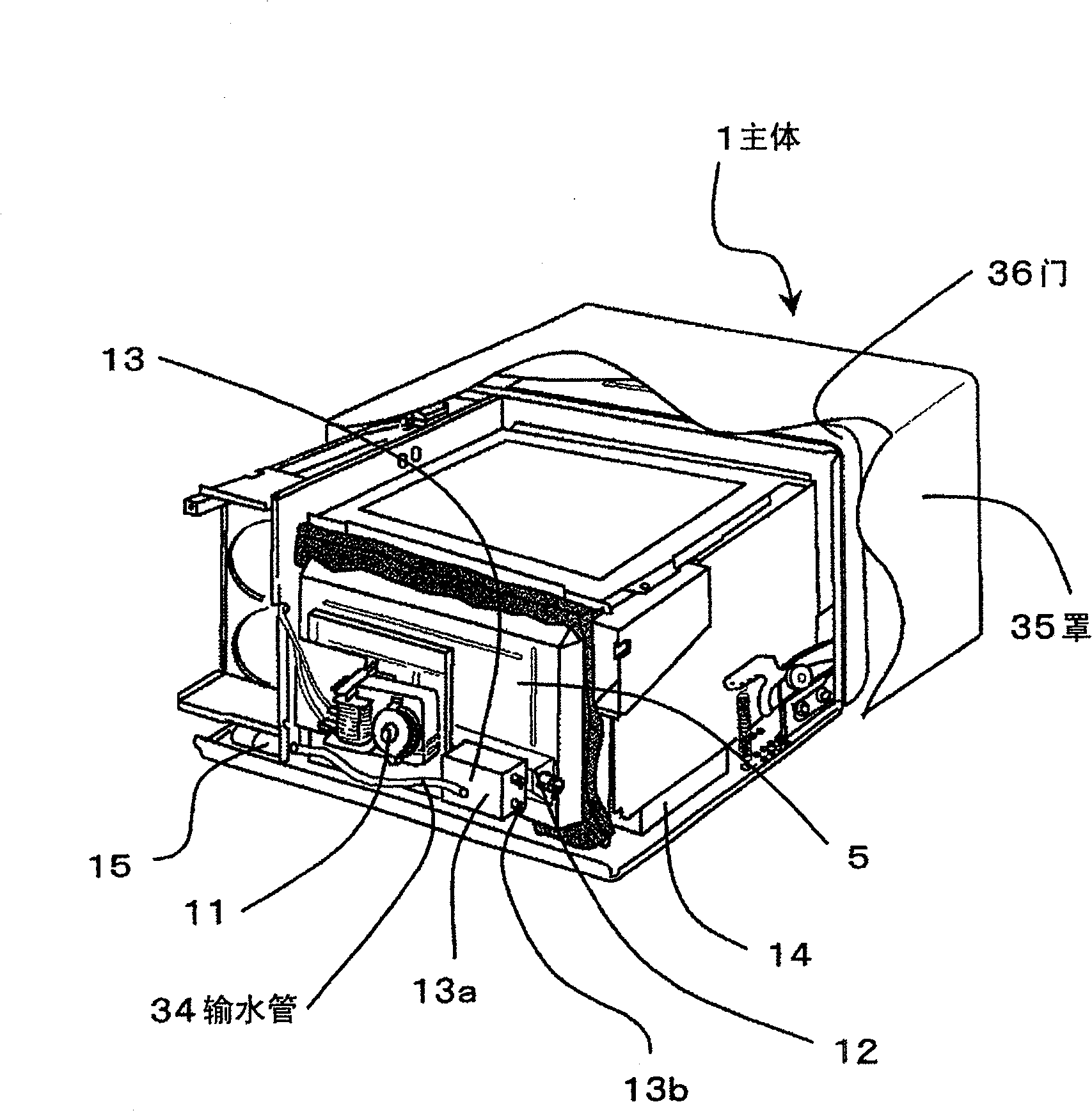
[0112] Hot air unit 5 and steam generating device 13 and figure 1 , Figure 4 Same, its structure is that the microwave sent from the magnetron 6 passes through the waveguide 7 and irradiates on the food to be cooked 4 from the side of the heating chamber 2 .

[0113] The rotary stage 32 is rotated by the stage motor 33 at its lower part, and a mass detection device 22 is arranged at its coaxial end, by which the mass detection device 22 can detect the objects loaded on the rotary stage 32. The weight of cooking object 4, its quality detection signal 23 is delivered to control device 27. The cooking method is the same as above Figure 7 The conte...


PUM


Abstract

The invention provides a heating cooker in a microwave oven or the like which supplies water vapor to the cooked object in the heating chamber and cooks it, which can simultaneously realize rapid moisturizing of the cooked object and high-efficiency heating and cooking of the cooked object, and simply Delicious cooked food can be provided. The heating cooker of the present invention is equipped with: a heating chamber (2) for accommodating the object to be cooked (4), a heating device (12) for heating the heating chamber (2), a steam generating device (13) for generating water vapor, and a water heater The air supply device (10) of the crushing device that gives impact to the steam and pulverizes it into finer; sprays the water vapor supplied from the steam generating device (13) to the outflow air (17) flowing from the air supply device (10) Blow, because of its impact, the water vapor is pulverized into finer pieces, and the fine water vapor (20) mixed with the outflow wind (17) is supplied into the heating chamber (2) to cook the food to be cooked (4).

Description

technical field [0001] The present invention relates to a heating cooker such as a microwave oven that supplies water vapor to an object to be cooked in a heating chamber for cooking. Background technique [0002] The original heating cooker, as shown in Patent Document 1-Japanese Patent Application Laid-Open No. 2004-316999, is provided with: a convection chamber with a convection fan and a convection heater for generating circulating air; The suction port and the blowing port on the boundary wall form a steam generating container that generates steam supplied to the heating chamber, and the steam generating container is provided near the suction port. [0003] In addition, as shown in Patent Document 2 - Japanese Patent Laid-Open No. 2004-028578, the structure includes: a high-frequency generator for emitting microwaves into the heating chamber, an evaporator for generating steam, a water supply unit for supplying water to the evaporator, and a water supply unit for contro...

Claims


Application Information

Patent Timeline
Patent Type & Authority Patents(China)
IPC IPC(8): A47J27/04F24C7/02
Inventor 木村秀行本间满田中佐知小泽圣堀切泰立川晃之伊丹启光长谷川雄一
Owner HITACHI HOME & LIFE SOLUTIONS INC
Why Eureka
Try Eureka