

Ink cartridge and inkjet printer
A technology for inkjet printers and ink cartridges, applied in printing and other directions, can solve problems such as incorrect ordering of inkjet head units
- Summary
- Abstract
- Description
- Claims
- Application Information
AI Technical Summary
Problems solved by technology
Method used
Image

Examples
no. 1 example
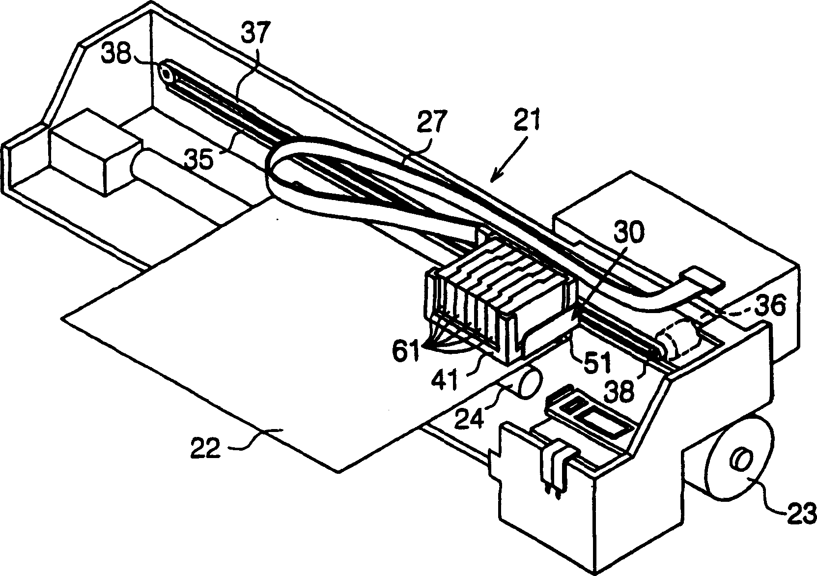
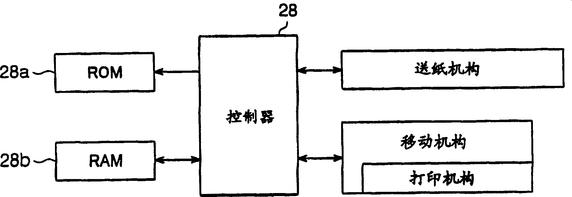
[0031] will now refer to Figure 1-9 A first embodiment of the present invention will be described. figure 1 The basic structure of the inkjet printer 21 is shown. As shown, the printer 21 includes a paper feeding mechanism that feeds paper 22 and a moving mechanism that moves a carriage 30, or a cassette accommodating portion. The carriage 30 includes a printing mechanism that ejects ink onto the paper 22 to print.
[0032] The paper feeding mechanism includes a paper feeding motor 23 , a paper feeding roller 24 and additional rollers (not shown). The paper feed motor 23 serves as a drive source. The paper feed roller 24 also serves as a platen. When the paper feed motor 23 is activated, the paper feed roller 24 and the additional roller rotate to convey the paper 22 .
[0033] The moving mechanism includes a guide element 35 , a carriage motor 36 , pulleys 38 and a timing belt 37 . The guide element 35 is parallel to the axis of the paper feed roller 24 . The carriage...
no. 2 example
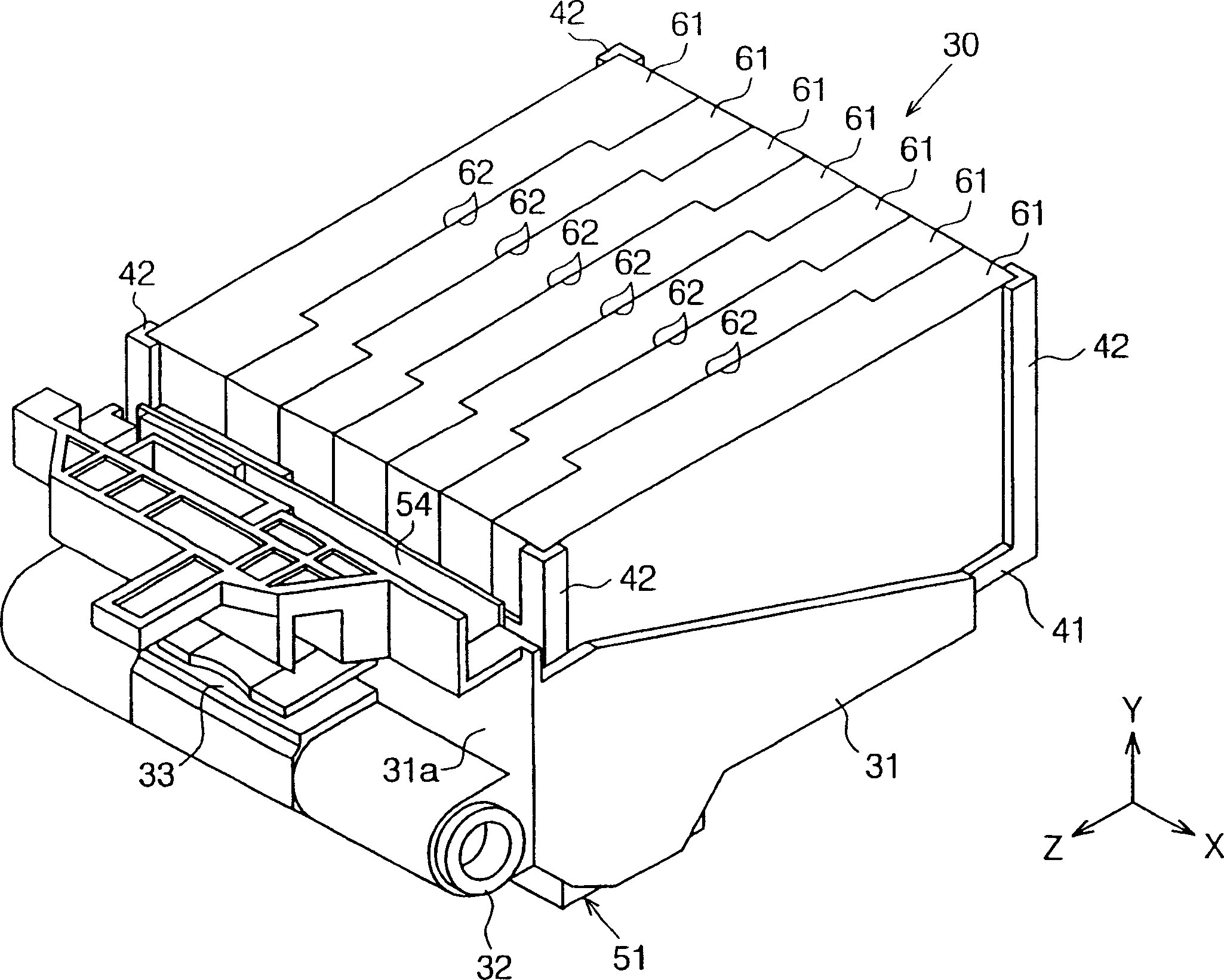
[0064] Refer to the attached Figure 10 A second embodiment of the present invention will be described. Mainly for the second embodiment and Figure 1-9 The differences of the first embodiment shown are described. Such as Figure 10 As shown, in the second embodiment, each protrusion 62a of these ink cartridges 61 is image 3 There are different sizes or different widths in the direction of the Z axis. Accordingly, each groove 62b of these ink cartridges 61 has a different width. In other words, the width of the protrusion 62a and the matching groove 62b of one pair of adjacent ink cartridges 61 is different from the width of the protrusion 62a and the matching groove 62b of another pair of adjacent ink cartridges 61 .
[0065] The protrusions 62a of adjacent ink cartridges 61 and the corresponding grooves 62b form a fitting structure for engaging these ink cartridges 61 . The width of the protrusion 62a and the matching groove 62b gradually decreases from the lowermost ...
no. 3 example
[0069] Refer to the attached Figure 11 A third embodiment of the present invention will be described. Mainly for the third embodiment and Figure 10 The differences of the second embodiment shown are described. Such as Figure 11 shown, with Figure 10 In contrast to the second embodiment shown, the widths of the protrusions 62a and matching grooves 62b gradually increase from the lowermost protrusion 62a and matching groove 62b to the uppermost one, as Figure 11 shown.
[0070] And, facing the ink cartridge 61 at one end of the cartridge support 41 (such as Figure 11 The uppermost ink cartridge 61) shown is larger than the remaining ink cartridges 61. Also, the groove 62b of this larger ink cartridge 61 is larger than the grooves 62b of the remaining smaller ink cartridges 61 . In addition, in each of the ink cartridges 61 except the two ink cartridges 61 facing the opposite end of the cartridge holder 41, the width of the protrusion 62a is larger than the width of ...
PUM
 Abstract
Description
Claims
Application Information