Flow rate calibrated, mechanically adjustable stormwater flow diverter

Inactive Publication Date: 2009-05-07
DUNCAN GREGORY S
View PDF5 Cites 5 Cited by
  • Summary
  • Abstract
  • Description
  • Claims
  • Application Information

AI Technical Summary

Benefits of technology

[0009]In view of the foregoing discussion, an object of this invention is to provide an improved stormwater diversion device that offer

Problems solved by technology

Because it is not practical to divert and treat larger events (high flow events e.g. 10-yr storm event), these high-flow events are not typically diverted and thus, will be conveyed in the typical manner, to a river, creek, or some other waterbody.
That being said, the problem remains to determine an easy to install, shallowly placed, accurate and repeatable method for separating lower storm events, requiring treatment, from the

Method used


Image

  • Flow rate calibrated, mechanically adjustable stormwater flow diverter
  • Flow rate calibrated, mechanically adjustable stormwater flow diverter
  • Flow rate calibrated, mechanically adjustable stormwater flow diverter

Examples


Embodiment Construction

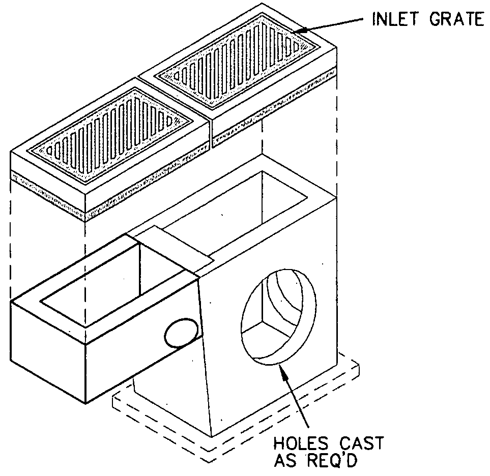
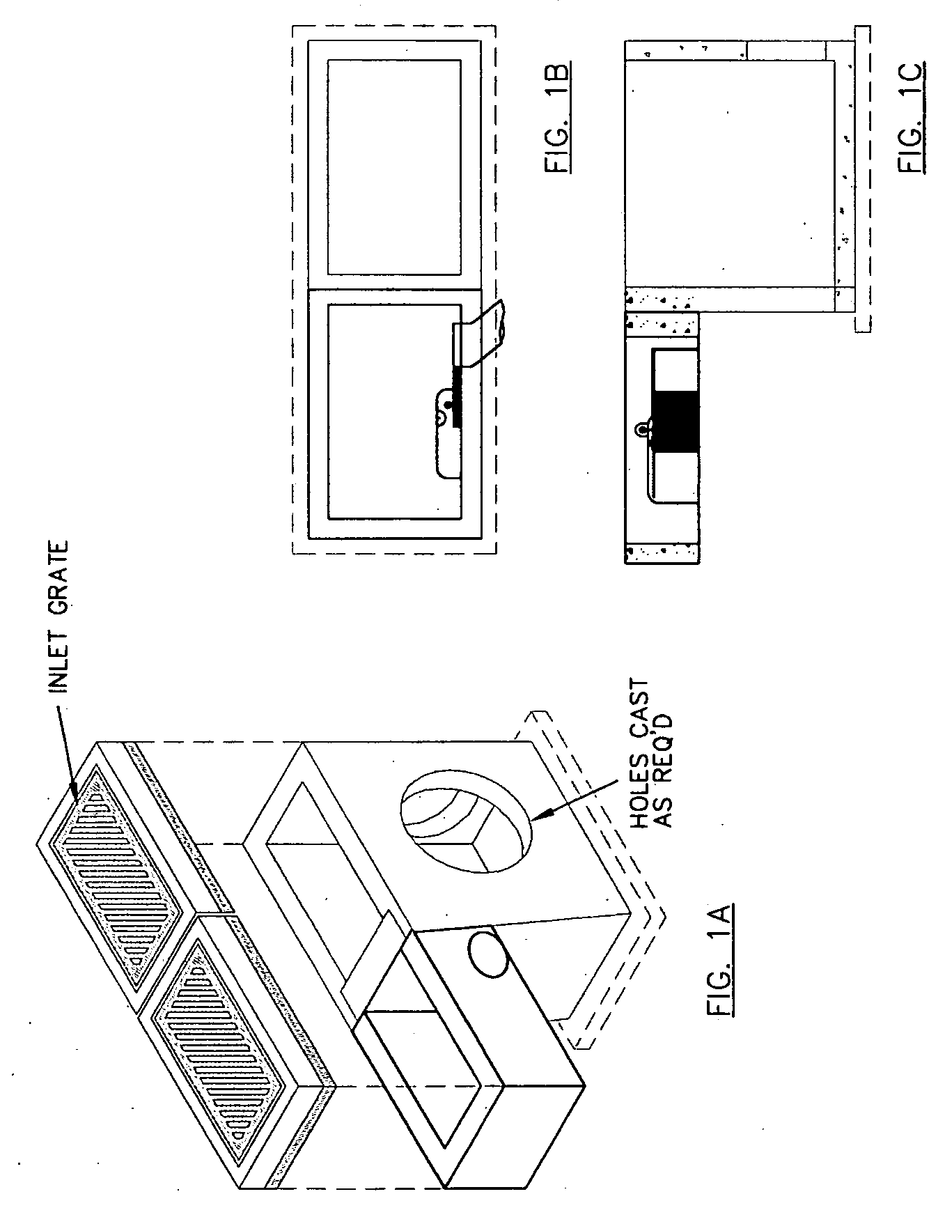
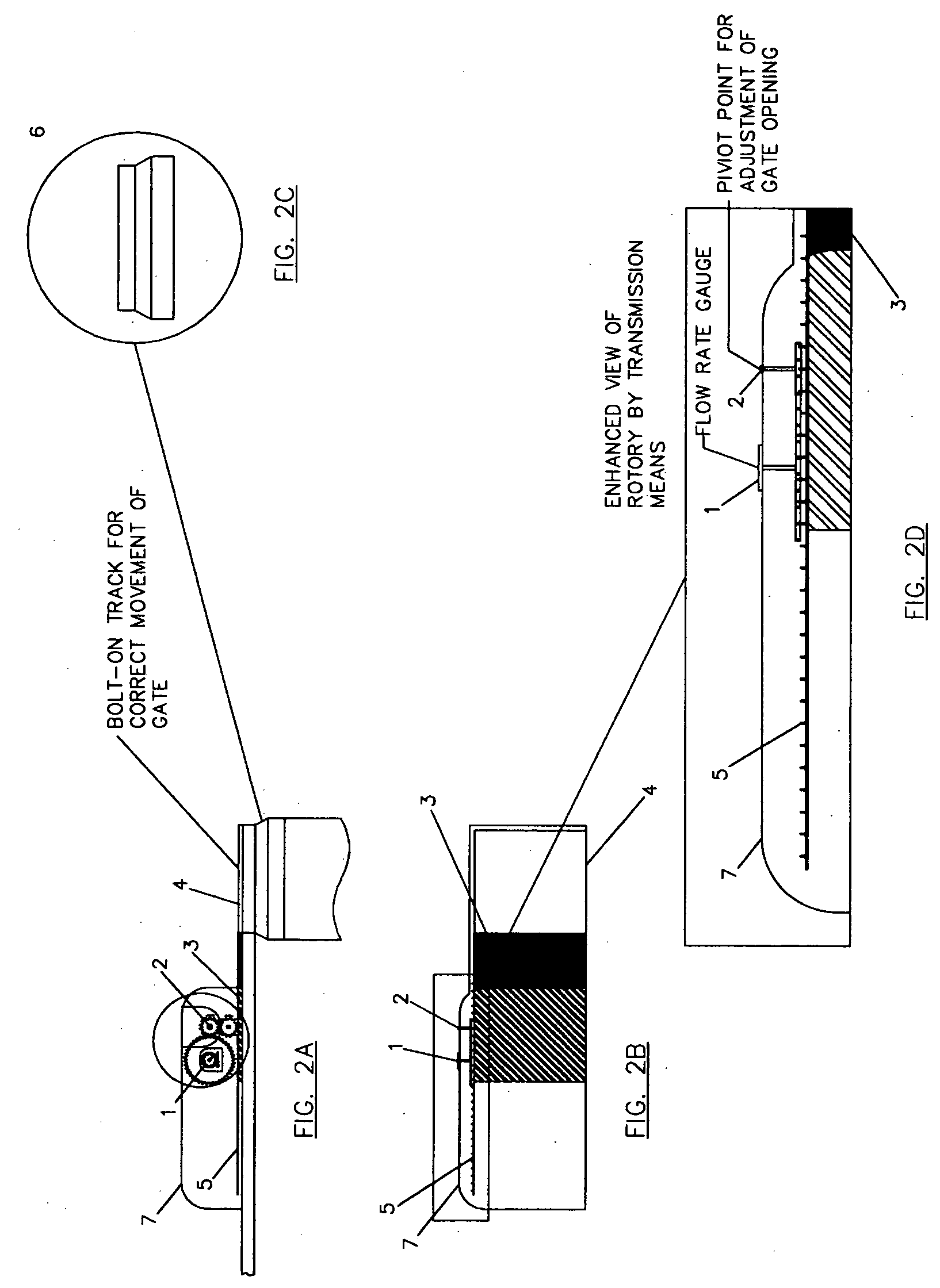
[0036]Referring now to the drawings, A flow rate gauge (1) is displayed on top of the apparatus clearly allows the installer to easily calibrate the device's potential flow rate to fit any particular need / situation without having to change the dimension of the box itself. Quite simply, after the device is fitted to the storm sewer structure, and the structure (e.g. inlet box) is installed in the field; the installer is merely required to use a tool to either accommodate more flow, by turning the adjustment nut (2) counter-clockwise resulting in the movement (opening) of the gate (3) along the track (4) or reduce the allowed flow rate, by turning clockwise resulting in the movement (closure) of the gate (3) along the track (4). While the movement of the gate adjusts the aperture (orifice) size the gauge (1) will continually allow the installer to observe what maximum flow rate will be achieved depending on what setting the gate (3) is left at. A qualified engineer, knowledgeable in h...


PUM

PropertyMeasurementUnit
Flow rateaaaaaaaaaa
Sizeaaaaaaaaaa

Abstract

An object of this invention is to provide an improved stormwater diversion device that offers a more precise, easy to install and accurate means for diverting stormwater flow than any of the aforementioned prior art techniques. Referring now to the drawings, a flow rate gauge (1) is displayed on top of the apparatus clearly allows the installer to easily calibrate the device's potential flow rate to fit any particular need/situation without having to change the dimension of the box itself. Quite simply, after the device is fitted to the storm sewer structure, and the structure (e.g. inlet box) is installed in the field; the installer is merely required to use a lug wrench to either accommodate more flow, by turning the adjustment nut (2) counter-clockwise resulting in the movement (opening) of the gate (3) along the track (4) or reduce the allowed flow rate, by turning clockwise resulting in the movement (closure) of the gate (3) along the track (4). While the movement of the gate adjusts the aperture (orifice) size, the gauge (1) will continually allow the installer to observe what flow rate would be achieved depending on the setting of the gate (3). A qualified engineer knowledgeable in hydrological methods would determine the selected flow rate required.

Description

BACKGROUND OF THE INVENTION[0001]1. Field of the Invention[0002]This invention relates to improvements in stormwater drainage structures (e.g., drainage inlets, manholes and the like), and specifically those that require diversion of a specific amount of stormwater flow.[0003]2. The Prior Art[0004]The reason behind the development of techniques in stormwater flow diversion or “flow-splitting” is as a result of addressing federal (EPA) mandate referred to as the Clean Water Act. Among the many provisions set out by the Clean Water Act, one of the more well known is the preservation of stormwater quality. As a result, over the years, it became commonplace for engineers to devise ways to separate lower flow events within storm sewers for the purposes of treating smaller rainfall events. These smaller events, sometimes known as the “water quality event” are separated from the storm sewer by a diversion structure and then conveyed to a water quality treatment facility. Because it is not ...

Claims


Application Information

Patent Timeline
IPC IPC(8): B01D35/157
CPCE03F2201/10E03F5/12
Inventor DUNCAN, GREGORY S.
Owner DUNCAN GREGORY S
Why Eureka
Try Eureka