Stacker crane and method for operating same

Active Publication Date: 2015-12-10
MURATA MASCH LTD
View PDF1 Cites 3 Cited by
  • Summary
  • Abstract
  • Description
  • Claims
  • Application Information

AI Technical Summary

Benefits of technology

This patent is about a stacker crane that has a simple structure to reduce stress on the connection between the mast and lower carriage during normal traveling. When the mast is upright for maintenance or installation, the support is raised and lowered to prevent stress on the connection. This allows for a lightweight mast and lower carriage, increased durability and reliability, and easier installation and maintenance. The displacement mechanism ensures that the mast is perpendicular to the lower carriage for stable operation. In particular, the mast is fixed directly above the lower drive wheel to minimize tilting force. Overall, this design improves the connection between the mast and lower carriage.

Problems solved by technology

Here, if the support is in contact with the lower rail, a strong force is exerted on the connection between the mast and the lower carriage, and therefore high rigidity is required at the connection.

Method used


Image

  • Stacker crane and method for operating same
  • Stacker crane and method for operating same
  • Stacker crane and method for operating same

Examples


Embodiment Construction

[0024]Hereinafter, preferred embodiments of the present invention will be described. The scope of the present invention should be construed based on the description of the claims and in accordance with the understanding of a person skilled in the art, with reference to the description of the specification and known techniques in the field.

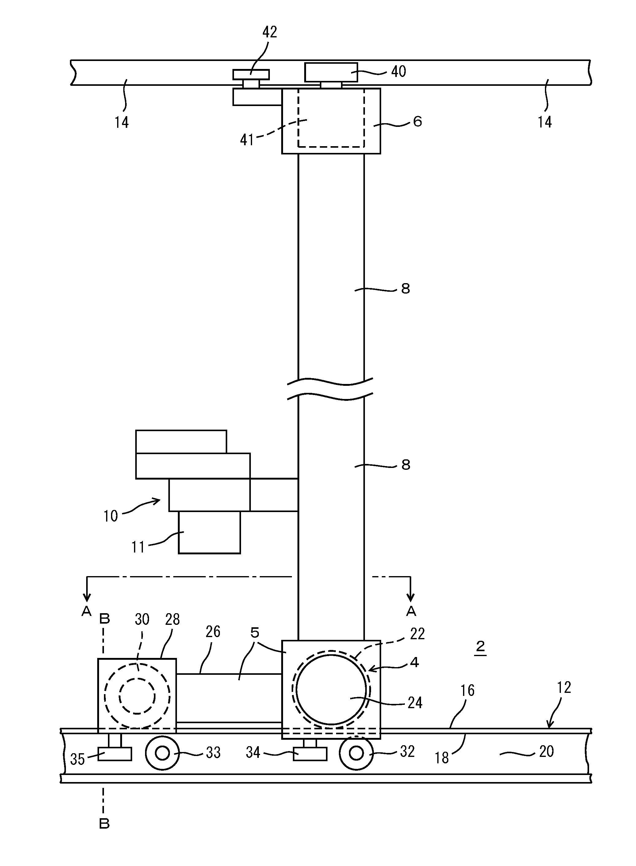
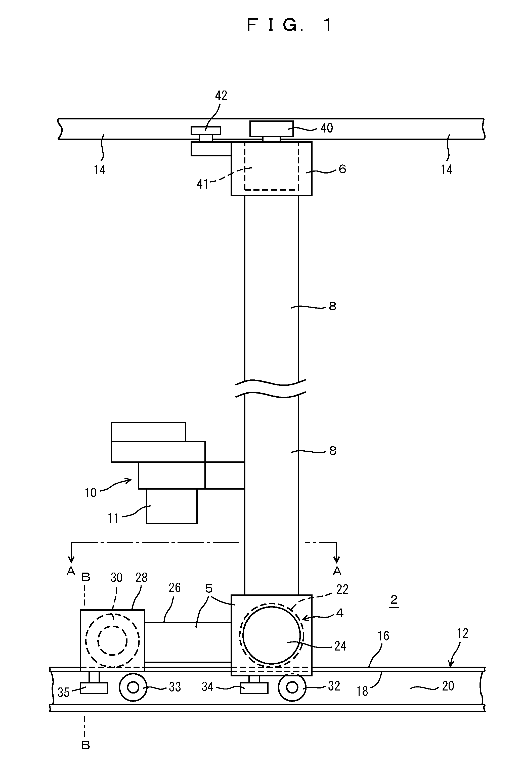
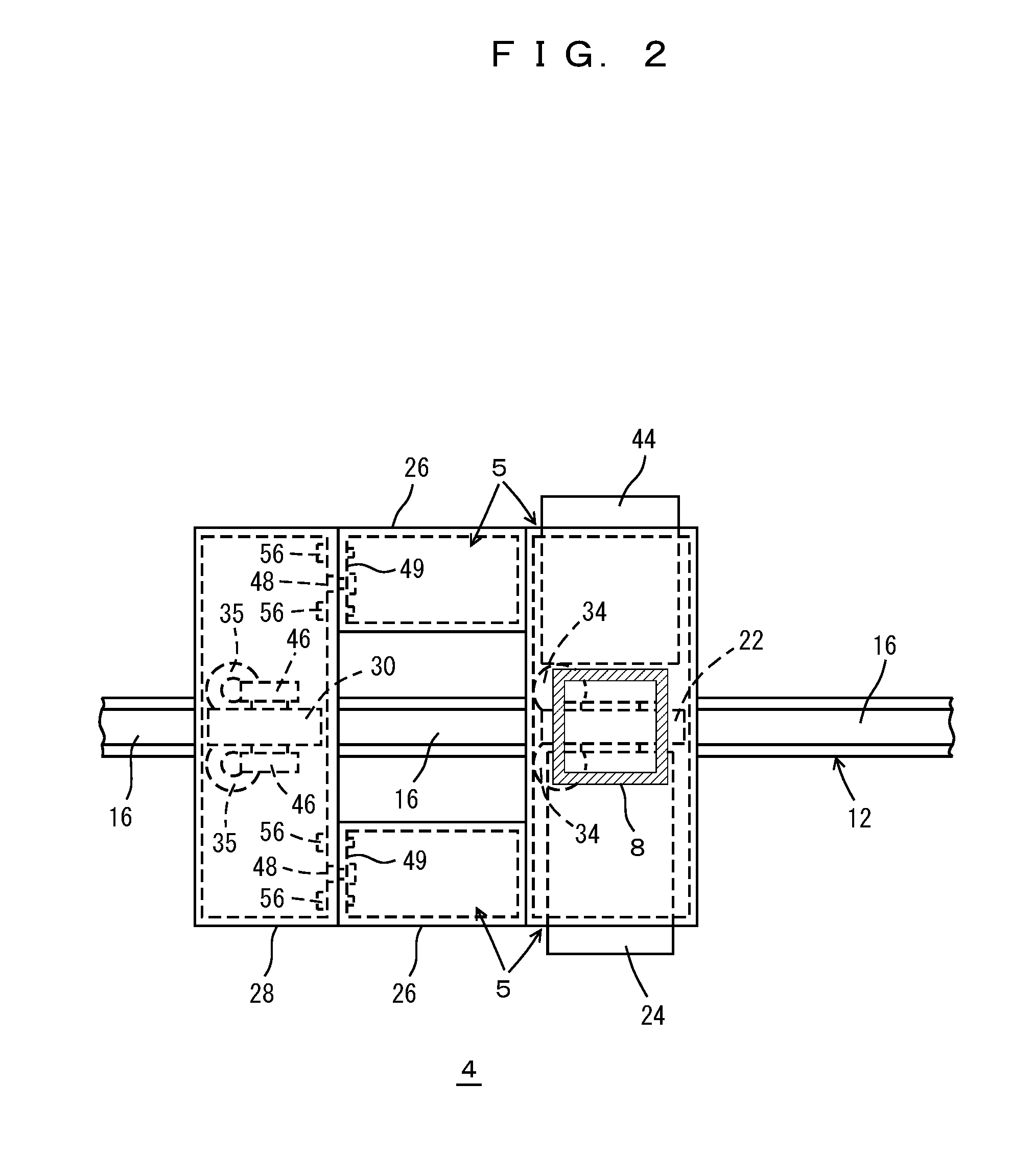
[0025]FIGS. 1 to 4 show a stacker crane 2 according to a preferred embodiment of the present invention. In the drawings, reference numeral 4 indicates a lower carriage including a main body 5 and a support 28, reference numeral 6 indicates an upper carriage, and a mast 8 fixed to the lower carriage 4 connects the upper and lower carriages 4 and 6. The mast 8 may be fixed to the upper carriage 6 or be attached pivotally to the upper carriage 6. The mast 8 may be a perpendicular tube that raises and lowers a transfer device 10 such as a SCARA arm, and instead of directly raising and lowering the transfer device 10, the mast 8 may raise and lower an e...


PUM


Abstract

A stacker crane includes a lower carriage including a lower drive wheel, a lower travel motor, and a support located apart from the lower drive wheel; an upper carriage including an upper drive wheel and an upper travel motor that drives the upper drive wheel; and a mast fixed to the lower carriage, standing upward from the lower carriage and connected to the upper carriage, and including a transfer device capable of moving up and down. A displacement mechanism that raises and lowers the support is provided on the lower carriage between a grounded position supported by a lower rail and a retracted position lifted off the lower rail. The support is lowered to the grounded position when the stacker crane is installed between the lower rail and the upper rail and when the stacker crane is stopped for maintenance, and the support is raised to the retracted position when the stacker crane is operated.

Description

BACKGROUND OF THE INVENTION[0001]1. Field of the Invention[0002]The present invention relates to a stacker crane and a method for operating the same, and in particular relates to reducing stress between a mast and a lower frame.[0003]2. Description of the Related Art[0004]The applicant has proposed providing travel motors in upper and lower carriages of a stacker crane so as to cause the upper and lower carriages to travel in a synchronized manner (See, for example, JP 2002-106414A). If the upper and lower carriages run out of synchronization, a strong force is exerted on the connection between the mast and the carriages, and therefore, in JP 2002-106414A, the mast is attached pivotally to the lower carriage.[0005]However, a pivotal mast is difficult to stand upright during installation of the stacker crane. Similarly, if the mast does not stand upright, it is difficult to perform maintenance on the stacker crane. Furthermore, if a mast with a large weight is to be pivoted, a large ...

Claims


Application Information

Patent Timeline
IPC IPC(8): B65G1/04
CPCB65G1/0407B66F9/072
Inventor TANAKA, HIROSHI
Owner MURATA MASCH LTD
Why Eureka
Try Eureka