Gear-change device

A technology of speed change device and speed change sleeve, which is applied in the direction of transmission parts, transmission control, and components with teeth, etc., which can solve the problems of cost, weight and tolerance disadvantages

Inactive Publication Date: 2007-01-24
HOERBIGER DRIVETRAIN MECHATRONICS B A
View PDF2 Cites 2 Cited by
  • Summary
  • Abstract
  • Description
  • Claims
  • Application Information

AI Technical Summary

Problems solved by technology

Therefore, for the interlocking of the shift fork shafts arranged at a distance from each other, complex mechanisms are required, which are disadvantageous in terms of cost, weight and tolerances

Method used


Image

  • Gear-change device
  • Gear-change device
  • Gear-change device

Examples


Embodiment Construction

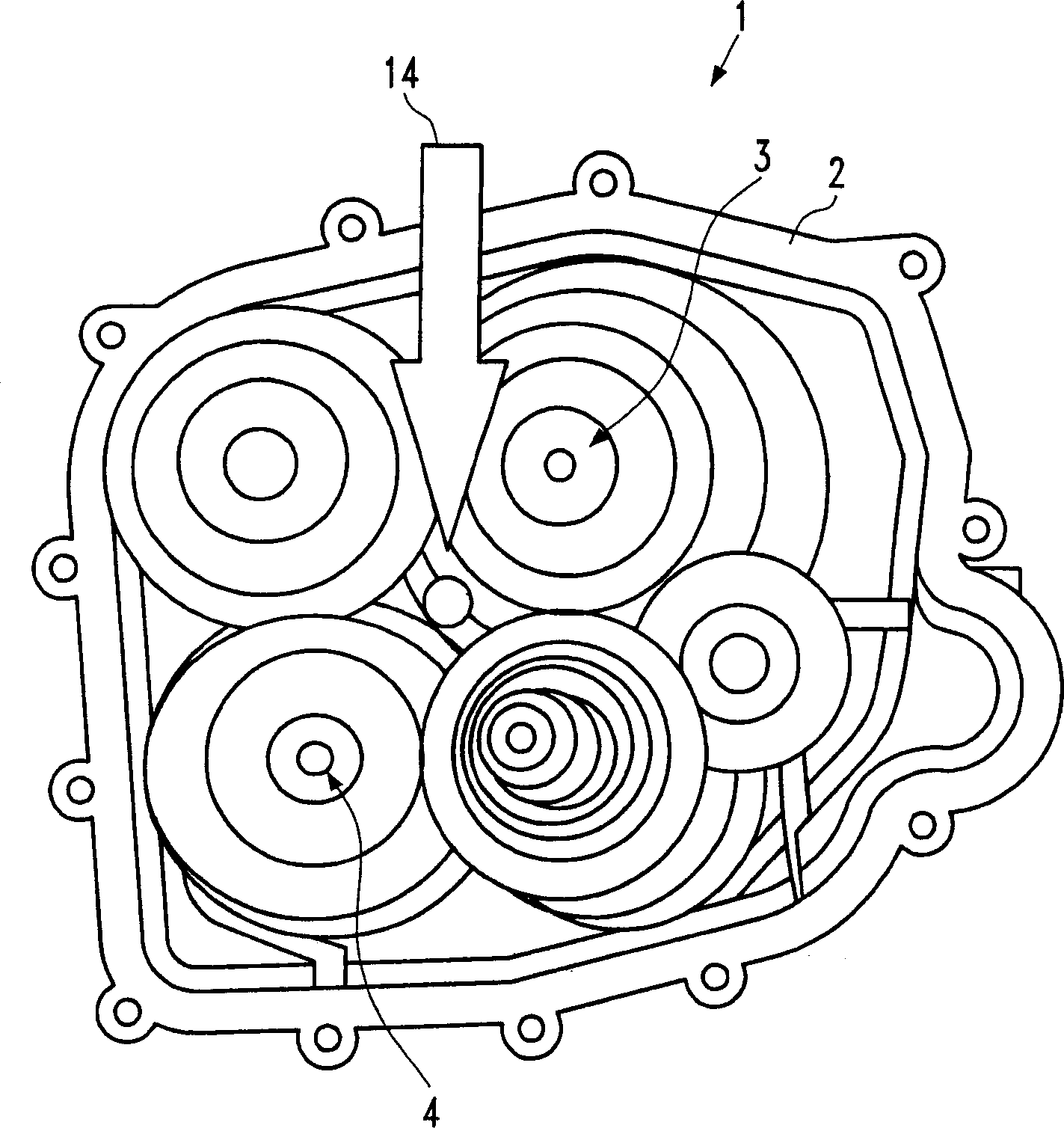
[0039] exist figure 1 In, an inventive transmission 1, in particular in the form of an automatic transmission, is shown in a schematic, somewhat simplified manner in order to illustrate the position of the inventive locking device 14 inside the transmission. The transmission device 1 includes a gearbox case 2, in an example, two gear shafts 3 and 4 are arranged inside the gearbox case 2.

[0040] A locking device 14, indicated by an arrow, is arranged between the pinion shafts 3 and 4, making possible the interlocking of the shifting sleeves arranged on the pinion shafts 3 and 4, which will be explained in more detail below. It goes without saying that the shifting device 1 includes all other elements of the shifting device, the description of which is omitted here since it is not useful for explaining the principles of the invention.

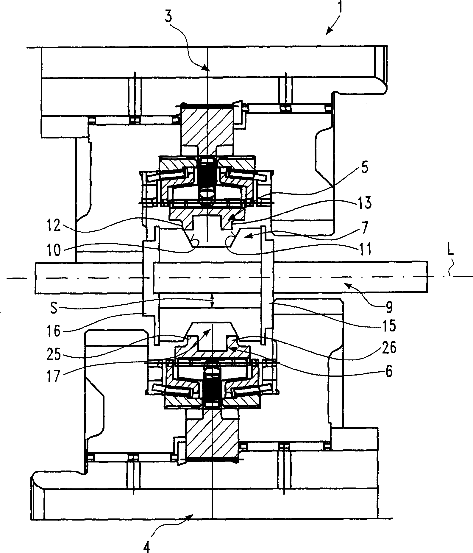
[0041] figure 2 shows the details of the transmission device 1 of the present invention, from figure 2 The pinion shafts 3 and 4 can agai...


PUM


Abstract

The present invention relates to a gear-change device ( 1 ) comprising a transmission housing ( 2 ), at least two neighboring gear shafts ( 3, 4 ) arranged in the transmission housing, and a respective gear-change sleeve ( 5, 6 ) per gear shaft ( 3, 4 ), wherein at least one locking element ( 7; 8 ) is arranged on a guide means ( 9 ) supported on the transmission housing ( 2 ), and by displacement of one ( 5 ) of the gear-change sleeves ( 5, 6 ) the respectively other one ( 6 ) of the gear-change sleeves ( 5, 6 ) is locked against an axial displacement on the gear shaft ( 4 ) thereof out of the neutral position.

Description

technical field [0001] The invention relates to a transmission and a locking device for the transmission. Such a transmission and such a locking device are known from EP 0 476 005 A. Background technique [0002] In transmissions, for safety reasons, it is required that only one gear should be shifted at a time during power flow. Incorrect meshing of other gears is prevented by corresponding locking devices. [0003] In existing designs, the locking operation is between the elements that move to operate the shift sleeve. The element can be a selector fork shaft, a selector fork shaft or a selector lever shaft. When the gears are engaged, the element is locked relative to the housing or a part fixed to the housing. [0004] Due to construction, there must always be a mechanically operative connection between the individual actuators, such as shift fork shafts and the like. [0005] However, in multi-shaft transmissions, for reasons of packaging, it is not always possible...

Claims


Application Information

Patent Timeline
Patent Type & Authority Applications(China)
IPC IPC(8): F16H61/22F16H63/34F16H63/36
CPCF16H63/36Y10T74/20018F16H57/02F16H57/025F16H63/32
Inventor 菲利普·德·马齐埃迪迪埃·热努乌
Owner HOERBIGER DRIVETRAIN MECHATRONICS B A
Why Eureka
Try Eureka