Manipulator having cross-in/cross-out and retardation controller

A deceleration control and control device technology, applied in the direction of program control manipulators, manipulators, manufacturing tools, etc., can solve the problems of reduced speed, large movement vibration, and difficult vibration control, etc., to achieve improved deceleration effect, good coordination accuracy, and high stop accuracy Effect

Inactive Publication Date: 2007-01-31
ZHEJIANG UNIV
View PDF0 Cites 6 Cited by
  • Summary
  • Abstract
  • Description
  • Claims
  • Application Information

AI Technical Summary

Problems solved by technology

However, the current in-and-out control of the manipulator control device of the injection molding machine has a large impact, the vibration is difficult to control, and the precision is poor, so deceleration control is urgently needed
The general manipulator controller does not have a deceleration function, so the horizontal entry and exit movements have large vibrations and poor precision.
There are some injection molding machine manipulator control devices in foreign countries and Taiwan with deceleration function, which is carried out through a pressure relief pneumatic solenoid valve (the deceleration position is detected by the sensor). To reduce the cylinder air pressure, thereby reducing the speed, this method needs to add an additional air valve, and the opening time of the deceleration valve cannot be precisely controlled, and the effect of deceleration function is not good enough
Because the air pressure of different manipulators may be different, the length of the horizontal in and out is also different. Sometimes the deceleration is early, so the movement speed of the manipulator is slow; sometimes the deceleration is late, so the deceleration effect is not obvious

Method used


Image

  • Manipulator having cross-in/cross-out and retardation controller
  • Manipulator having cross-in/cross-out and retardation controller

Examples


Embodiment Construction

[0013] With reference to accompanying drawing, the present invention will be described in detail below:

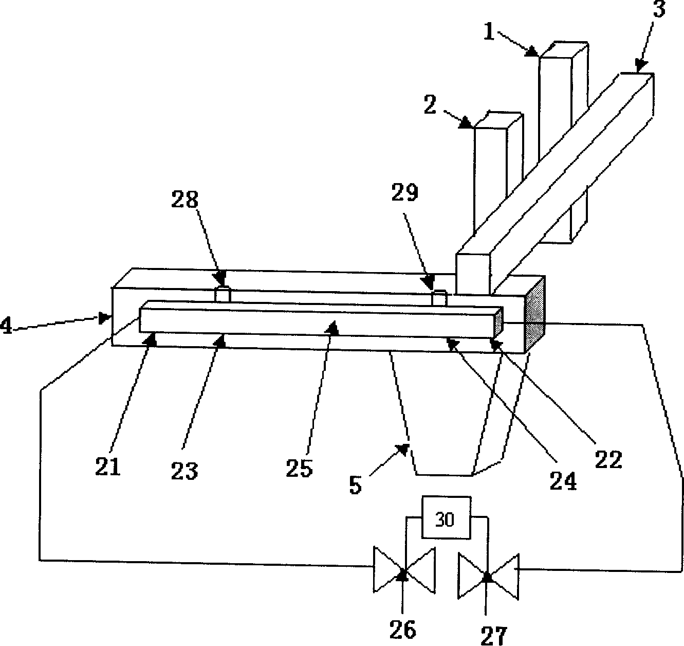
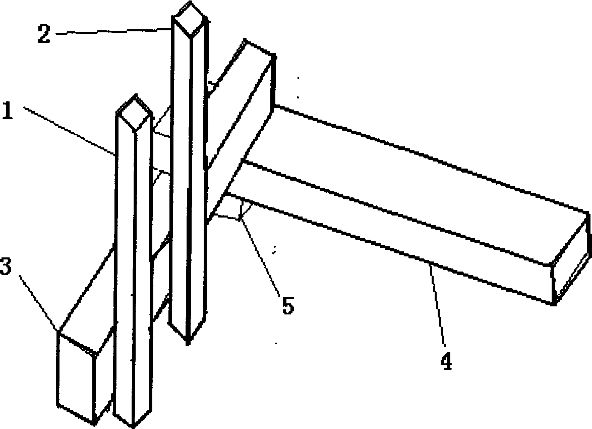
[0014] A manipulator with a cross-in and cross-out deceleration control device, with two retrieving arms, the main arm 1 and the auxiliary arm 2, the main arm 1 and the auxiliary arm 2 are installed on the drawing beam 3, and the drawing beam 3 is installed on the cross beam 4 above. The main arm 1 and the auxiliary arm 2 can move up and down, and they can also move forward and backward on the drawing beam 3. The drawing beam 3 can move in and out horizontally on the beam 4, so that the manipulator has X, Y , the degree of freedom movement in the Z direction, all movements are controlled by the air pressure solenoid valve through the cylinder 25 and driven by air pressure. The base 5 of the manipulator is installed on the injection molding machine, and the base 5 and the beam 4 are fixed together to support the whole manipulator. The cross-in and cross-out action is move...


PUM


Abstract

A manipulator with transverse-in and transverse-out speed-reducing controller is composed of control unit, primary arm, secondary arm, leading-pulling bean, transverse beam with transverse-out and transverse-in deceleration signal approximate switch's sensors, base and cylinder with transverse-in and transverse-out electromagnetic valves. Said sensors and electromagnetic valves are connected to said control unit.

Description

technical field [0001] The invention relates to an injection molding machine manipulator, and more specifically, relates to a manipulator with a transverse entry and transverse exit deceleration control device. Background technique [0002] The fully pneumatic injection molding machine manipulator usually has one or two mechanical arms. The mechanical arm is installed on the beam. The mechanical arm has two degrees of freedom, front and rear, and up and down. has three degrees of freedom. The manipulator picks up the product at the in position and the product in the out position, so the stability and high precision of the in and out movements are particularly important. However, the current in-and-out control of the manipulator control device of the injection molding machine has a large impact, the vibration is difficult to control, and the precision is poor, so deceleration control is urgently needed. The general manipulator controller does not have a deceleration functio...

Claims


Application Information

Patent Timeline
Patent Type & Authority Applications(China)
IPC IPC(8): B25J9/00B29C45/40
Inventor 彭勇刚韦巍
Owner ZHEJIANG UNIV
Why Eureka
Try Eureka