Tyre air inflating device of tyre road pressing machine

A technology for tire rollers and inflators, which is used in transportation and packaging, vehicle maintenance, vehicle maintenance/repair, etc., can solve problems such as poor sealing, inability to adjust inflation pressure, inconvenient use and operation, and maintain working pressure. , easy to use effect

Inactive Publication Date: 2007-01-31
SANY HEAVY IND CO LTD (CN)
View PDF0 Cites 4 Cited by
  • Summary
  • Abstract
  • Description
  • Claims
  • Application Information

AI Technical Summary

Problems solved by technology

The prior art has the following problems: 1. The inflation pressure cannot be adjusted, and cannot adapt to the tire pressure requirements of different working conditions
2. It is inconvenient to use and operate. It is necessary to use a special tool to open the valve core 6 of the tire before use, and to close the valve core

Method used


Image

  • Tyre air inflating device of tyre road pressing machine
  • Tyre air inflating device of tyre road pressing machine
  • Tyre air inflating device of tyre road pressing machine

Examples


Embodiment 1

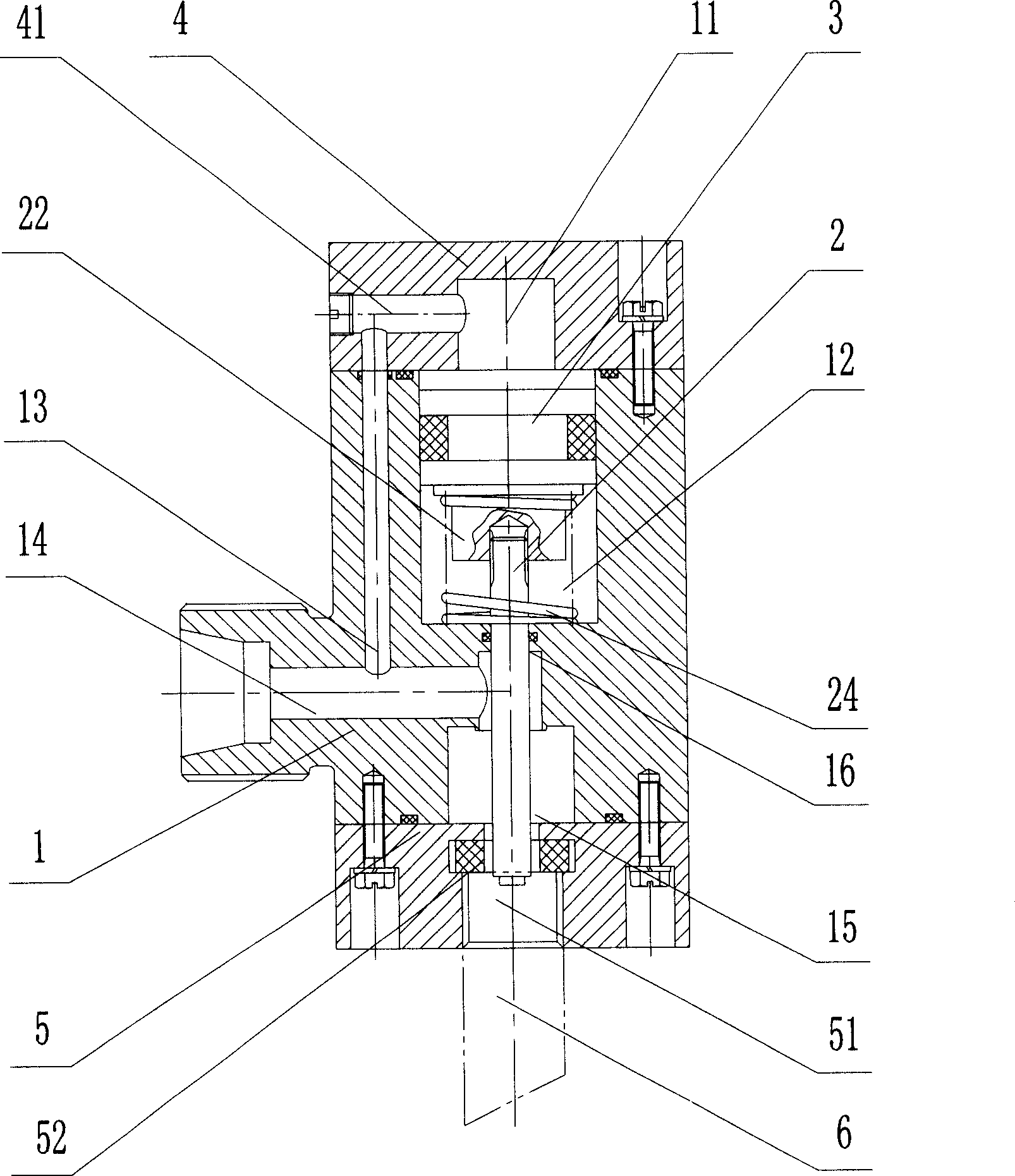
[0024] Embodiment 1: as figure 2 As shown, the tire inflation device of the tire roller of the present invention includes a valve body 1, a valve stem 2 and a piston 3; 3. Divide the upper part of the inner cavity of the valve body 1 into a pressure accumulator chamber 11 and an elastic chamber 12; the two ends of the valve body 1 are connected with an upper end cover 4 and a lower end cover 5 by bolts, and the valve body 1 is also provided with a valve body air guide channel 13. One end of the valve body air guide channel 13 communicates with the air inlet 14 provided on the valve body 1, and the other end communicates with the pressure storage chamber 11 through the end cover air guide channel 41 opened on the upper end cover 4; the upper end of the valve stem 2 is threaded A guide seat 22 is connected, and a spring 24 is set on the guide seat 22. The contact area between the guide seat 22 and the piston 3 is large, which ensures that the valve stem does not deflect during ...

Embodiment 2

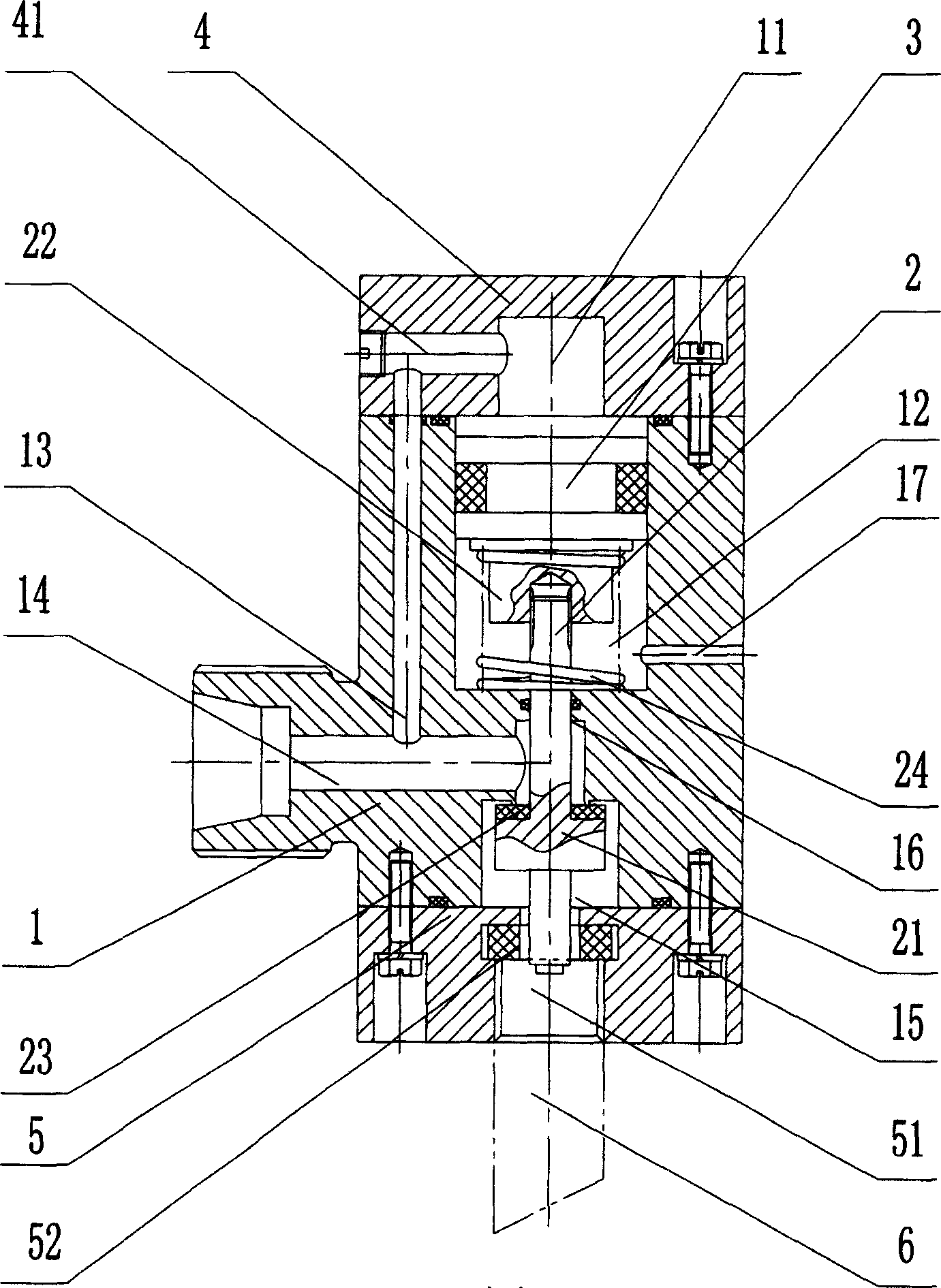
[0026] Embodiment 2: as image 3 As shown, the tire inflation device of the tire roller of the present invention includes a valve body 1, a valve stem 2 and a piston 3; 3. Divide the upper part of the inner cavity of the valve body 1 into a pressure accumulator chamber 11 and an elastic chamber 12; the two ends of the valve body 1 are connected with an upper end cover 4 and a lower end cover 5 by bolts, and the valve body 1 is also provided with a valve body air guide channel 13. One end of the valve body air guide channel 13 communicates with the air inlet 14 provided on the valve body 1, and the other end communicates with the pressure storage chamber 11 through the end cover air guide channel 41 opened on the upper end cover 4; the upper end of the valve stem 2 is threaded A guide seat 22 is connected, and a spring 24 is set on the guide seat 22. The contact area between the guide seat 22 and the piston 3 is large, which ensures that the valve stem 2 does not deflect during...


PUM


Abstract

The present invention relates to a tyre inflation unit of tyre street roller. It includes valve body and valve stem and piston which are mounted in the interior of valve body, the piston is positioned in the upper end of valve stem. The described piston can be used for dividing upper portion of internal cavity of valve body into pressure accumulating cavity and elastic force cavity. Two ends of said valve body are equipped with an upper end cover and a lower end cover, and said valve body has a valve body air guide channel, one end of said valve body air guide channel is communicated with air inlet set on the valve body, and its another end is communicated with pressure accumulating cavity by means of end cover air guide channel set on the upper end cover, the lower end of the valve stem is extended to air outlet set on the lower end cover.

Description

technical field [0001] The invention mainly relates to the field of road construction machinery, in particular to a tire inflation device of a tire road roller. Background technique [0002] Such as figure 1 As shown, the tire inflation device of the existing tire roller includes a valve body 1, a fixed nut 7 installed on the upper end of the valve body 1, an adjusting screw 9 installed in the fixed nut 7, and a piston installed in the valve body 1. 3 and stem 2. The prior art has the following problems: 1. The inflation pressure cannot be adjusted, and cannot meet the requirements of tire pressure in different working conditions. 2. It is inconvenient to use and operate. It is necessary to use a special tool to open the valve core 6 of the tire before use. After inflation, the valve core 6 must be closed. 3. The sealing is not good. If the valve core 6 is damaged, the tire cannot be guaranteed. Minimum air pressure, causing the tire roller to not work properly. The abov...

Claims


Application Information

Patent Timeline
IPC IPC(8): B60S5/04
Inventor 曹锦明王新明陈乐尧段乾坤
Owner SANY HEAVY IND CO LTD (CN)
Why Eureka
Try Eureka