
Drive device for combing machine

A driving device and combing machine technology, which is applied in the field of combing machines to achieve the effect of reducing the number

Inactive Publication Date: 2007-01-31
MASCHINENFABRIK RIETER AG
View PDF1 Cites 5 Cited by
  • Summary
  • Abstract
  • Description
  • Claims
  • Application Information

AI Technical Summary

Problems solved by technology

This design also has the disadvantages described above, in which case it is necessary to operate two sliver placement devices arranged spatially apart from one another
This results in more effort or additional maintenance tasks to be overcome by the operator in order to supply and remove the tank

Method used


Image

  • Drive device for combing machine
  • Drive device for combing machine
  • Drive device for combing machine

Examples


Embodiment Construction

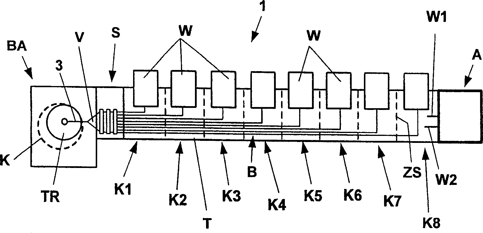
[0032] figure 1 is a plan view of a known combing machine 1 with a total of eight combing heads K1 to K8 arranged next to each other, each combing head having a lap roller W for processing in front of it. The individual devices of the combing heads K1 to K8 (such as clamps, circular combs, detaching rollers, lap rollers, transfer rollers, etc.) are driven by drive A via shafts extending longitudinally to the combing heads, schematically shown in the figure Two of these axes are W1 and W2. The driving device A basically includes a main motor and a transmission. In the case of a combing head, generally a "gage" and a plurality of gauges may be involved, which together form a longitudinal section of the combing machine for the carding process of the fibrous material.

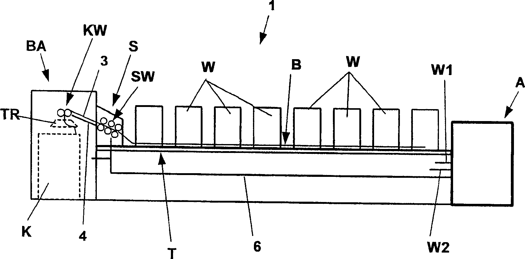
[0033] Above the table T, the sliver B formed at the individual combing heads K1-K8 is guided to the drafting device S. especially if image 3As shown in , the table T guides the sliver B obliquely upwards. A...


PUM


Abstract

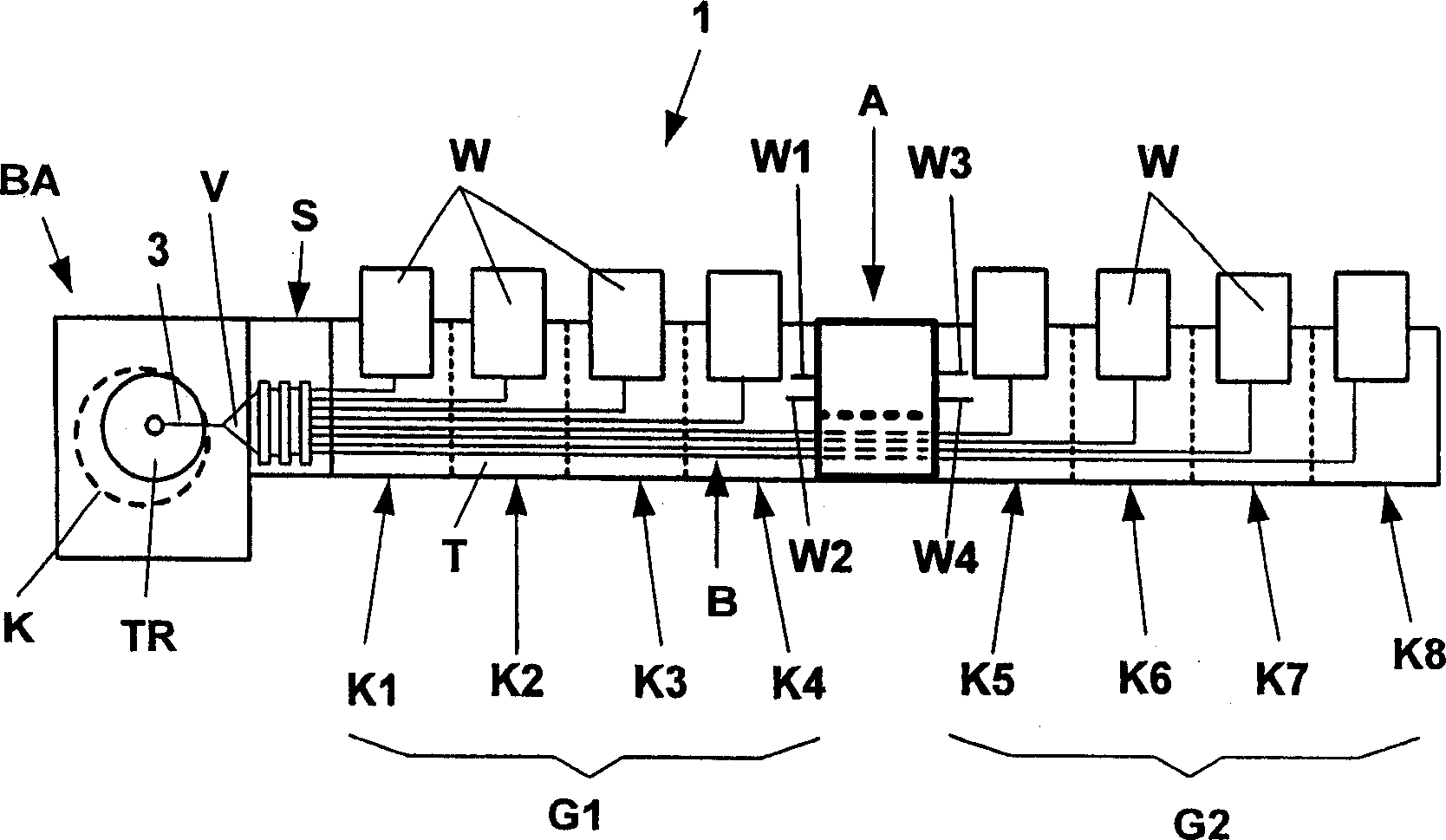
The present invention relates to a comber (1) which comprising a plurality of combing heads (K1-K8) disposed adjacent to each other in a row, the combing heads are driven by a driving device, wherein a sliver (B) formed on the combing heads is supplied to drafting device by the guider (T, FB), then the sliver (3) on the drafting device is transported to the placing device (BA) on the end of the comber. In order to reduce the driving load meanwhile keep the operability of the drafting device and the sliver placing device, at least two groups of combing heads (G1,G2) are provided, each of the groups are connected to the driving device through at least one common driving element, the driving device is arranged between a group of combing heads (G2) and the sliver placing device (BA).

Description

technical field [0001] The invention relates to a combing machine comprising a plurality of combing heads arranged next to each other in a row, the combing heads being driven by drive means, wherein the slivers formed on the respective combing heads are supplied to the drafting via guides. device, while the sliver formed on the drafting device is provided to the sliver placement device at the end of the comber. Background technique [0002] In a practically used combing machine, the combing heads of the combing machine, which are arranged next to each other in a row, are driven by a drive device arranged on the end of the combing machine. The combing head unit is driven by a shaft that starts from the transmission housing of the drive and travels longitudinally to the row of combing heads. The drafting unit is positioned at the other end of the combing machine or at the end of the row of combing heads and tensions the sliver conveyed from the individual combing heads and su...

Claims


Application Information

Patent Timeline
IPC IPC(8): D01G19/00D01G19/06
CPCD01G19/26
Inventor D·索默W·斯拉维克
Owner MASCHINENFABRIK RIETER AG
Learn More