Method of light plate-to-light plate time slot time division optimizing configaration of SDH system

A technology for optimizing configuration and time slot configuration, which is applied in time division multiplexing systems, electrical components, multiplexing communication, etc., can solve the problems of time division resource waste and achieve the goals of improving success rate, saving time and cost Effect

Inactive Publication Date: 2007-01-31
GLOBAL INNOVATION AGGREGATORS LLC
View PDF0 Cites 3 Cited by
  • Summary
  • Abstract
  • Description
  • Claims
  • Application Information

AI Technical Summary

Problems solved by technology

[0009] The purpose of the present invention is to overcome the shortcoming of wasting time-division resources in general time slot configuration methods, and provide a time-division resource optimization method for realizing optical board-to-optical board time slot configuration in an SDH system

Method used


Image

  • Method of light plate-to-light plate time slot time division optimizing configaration of SDH system
  • Method of light plate-to-light plate time slot time division optimizing configaration of SDH system
  • Method of light plate-to-light plate time slot time division optimizing configaration of SDH system

Examples


example 1

[0057] Example 1. Optimized use of time division between optical board TU level signal crossover to optical board TU level signal

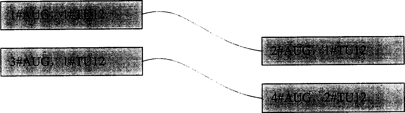
[0058] Such as image 3 As shown, the following two time slot commands are issued:

[0059] 1: Light board 1#AUG, 1#TU12 cross to light board 2#AUG, 1#TU12

[0060] 2: Light board 3#AUG, 1#TU12 cross to light board 4#AUG, 2#TU12

[0061] According to the light board to light board time slot configuration method 1#AUG 1#TU12 crosses to 2#AUG 1#TU12, because the position of the time slot number has not changed (1#TU12 corresponds to 1#TU12), therefore, the first time slot command The configuration can be from 1#AUG to 2#AUG directly, without passing time. And 1#TU12 of 3#AUG is crossed to 2#TU12 of 4#AUG. Because the position of the time slot number has been adjusted (1#TU12 corresponds to 2#TU12), the configuration of the second time slot command is changed from 1#AUG You must pass the time to complete it. The configuration result 1#AUG is directly spa...

example 2

[0063] Example 2. Application of time division AU time slot stream into time division module

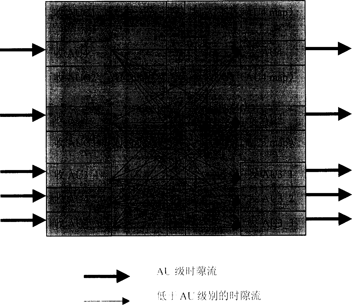
[0064] Assume that there are 3 different time-division marked AU4 time-division timeslot streams, which enter two time-division modules with a cross-over capacity of 6*6.

[0065] 1: AU4 No. 1, AU4 No. 2, AU4 No. 3, AU4 No. 4

[0066] 2: No. 3 AU4, No. 6 AU4, No. 7 AU4

[0067] 3: AU4 No. 1, AU4 No. 2, AU4 No. 5

[0068] According to the time division AU time slot flow into the time division module method, such as Figure 5 Shown. When entering the time-division module for the first time, the matching numbers of the three time-slot streams are all 0. First, the first time-slot stream enters the time-division module and occupies 4 time-division resources in the first time-division module. The time-slot stream 2 is calculated according to the above method , The matching number of 3 is 1 and 2. The time slot stream with the largest matching number is selected to enter the time division modu...


PUM


Abstract

The invention relates to a method for implementing plate-to-plate time gap time division optimization configuring method for an SDH system, mainly comprising: in mapping mode, making time gap configuration on AUG unmarked by time division and space division; for time gap flow of each time division AU, calculating corresponding matching number, where the matching number is number of time gap flows which have entered time division module and have the same AU number, and the matching number determines sequence of time division time gaps to enter the time division module; according to the matching numbers, in sequence arranging AU time gap flows to enter the time division module; if all time gap data flows are able to enter the time division module, the time division configuration succeeds and otherwise it returns failure information. And the invention makes improvement in time division resources utilization, saving time division resources and cost, and raising service configuration success rate.

Description

Technical field [0001] The invention relates to a method for optimizing the use of resources, in particular to an optical synchronous digital transmission network system in the field of communication to realize an optical board to an optical board time slot time division optimization configuration method. Background technique [0002] In an optical synchronous digital transmission network, if there is data transmission between two network elements and within the network elements, time slot configuration must be performed. The function of the time slot configuration is to determine the specific cross path of the outgoing and incoming time slots for a given outgoing and incoming time slot. [0003] The position of the outgoing time slot and incoming time slot may be on the optical board or on the tributary board. A certain time slot can directly complete the crossover of exit and entry through the space division crossover matrix, or can complete the crossover between exit and entry...

Claims


Application Information

Patent Timeline
Patent Type & Authority Applications(China)
IPC IPC(8): H04J3/08
Inventor 杜建平
Owner GLOBAL INNOVATION AGGREGATORS LLC
Why Eureka
Try Eureka