Drive device for ultrasonic linear motor

A driving device and linear motor technology, applied in piezoelectric effect/electrostrictive or magnetostrictive motors, generators/motors, piezoelectric devices/electrostrictive devices, etc., can solve the problems of fast wear, short life, Large wear and tear of sliding parts, etc.

Inactive Publication Date: 2007-01-31
HONDA MOTOR CO LTD
View PDF0 Cites 4 Cited by
  • Summary
  • Abstract
  • Description
  • Claims
  • Application Information

AI Technical Summary

Problems solved by technology

[0008] However, since the load of the base body 103 (ultrasonic vibrator 112) is borne by the sliding parts 105, 105, the sliding parts are greatly worn out during long-term use.
Especially in an environment such as a factory with many foreign objects (such as dust) floating around, there are problems of rapid wear and short life after long-term use

Method used


Image

  • Drive device for ultrasonic linear motor
  • Drive device for ultrasonic linear motor
  • Drive device for ultrasonic linear motor

Examples


Embodiment Construction

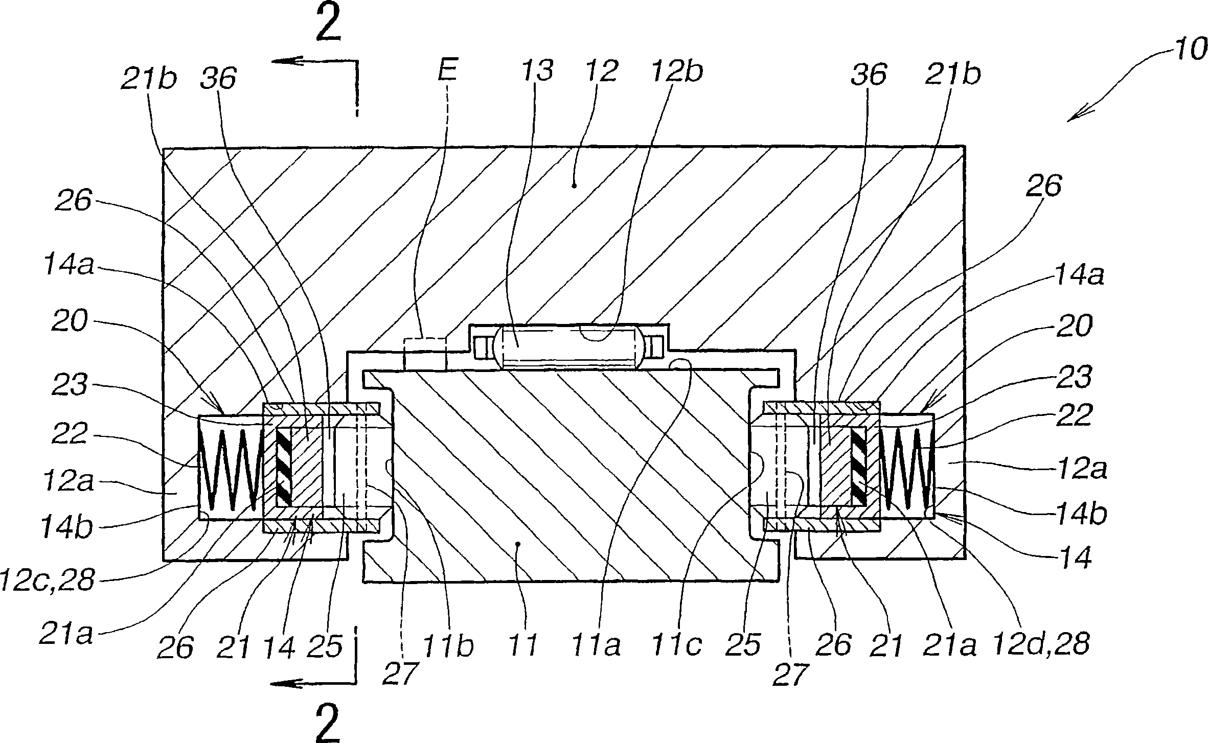
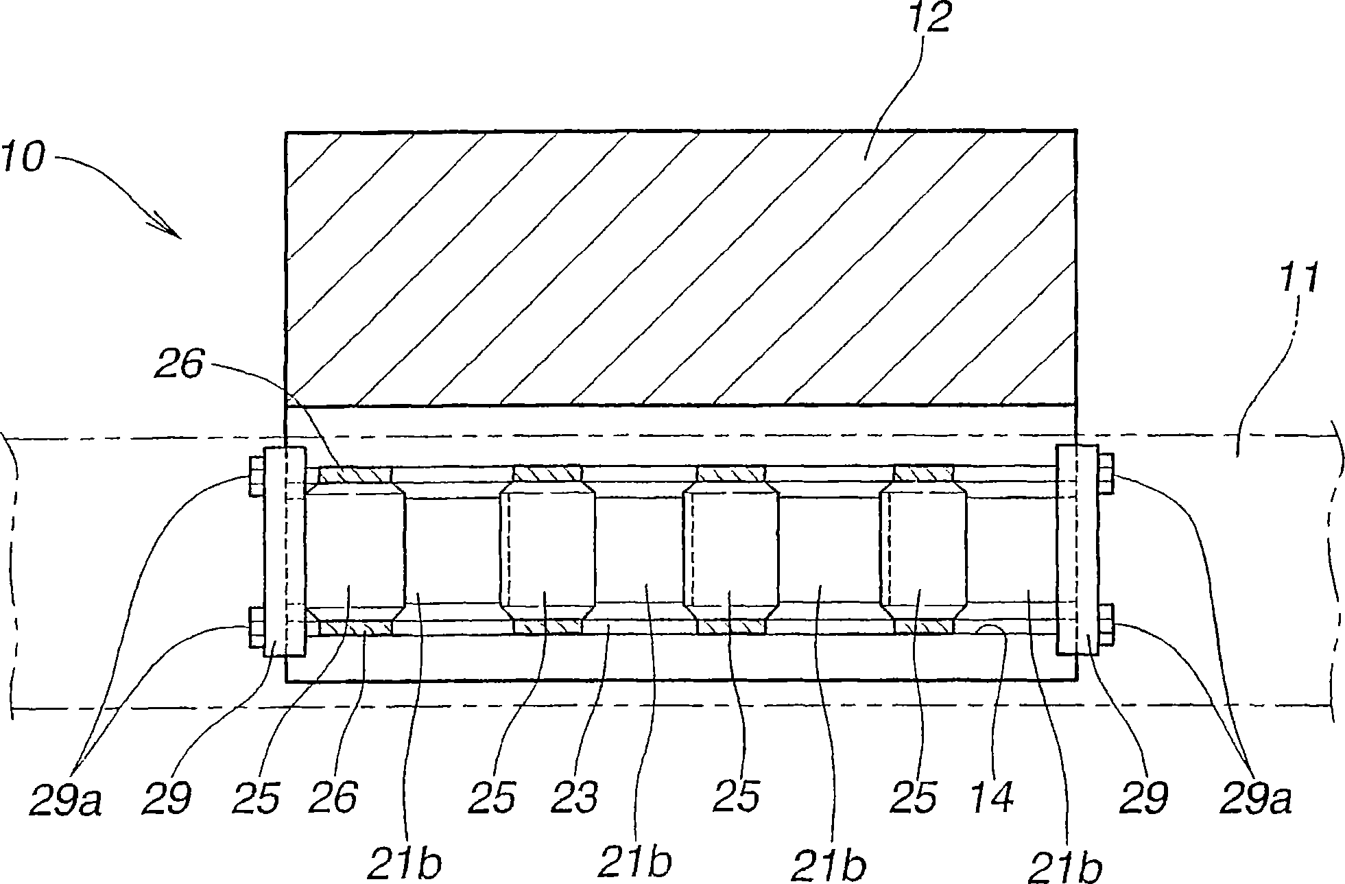
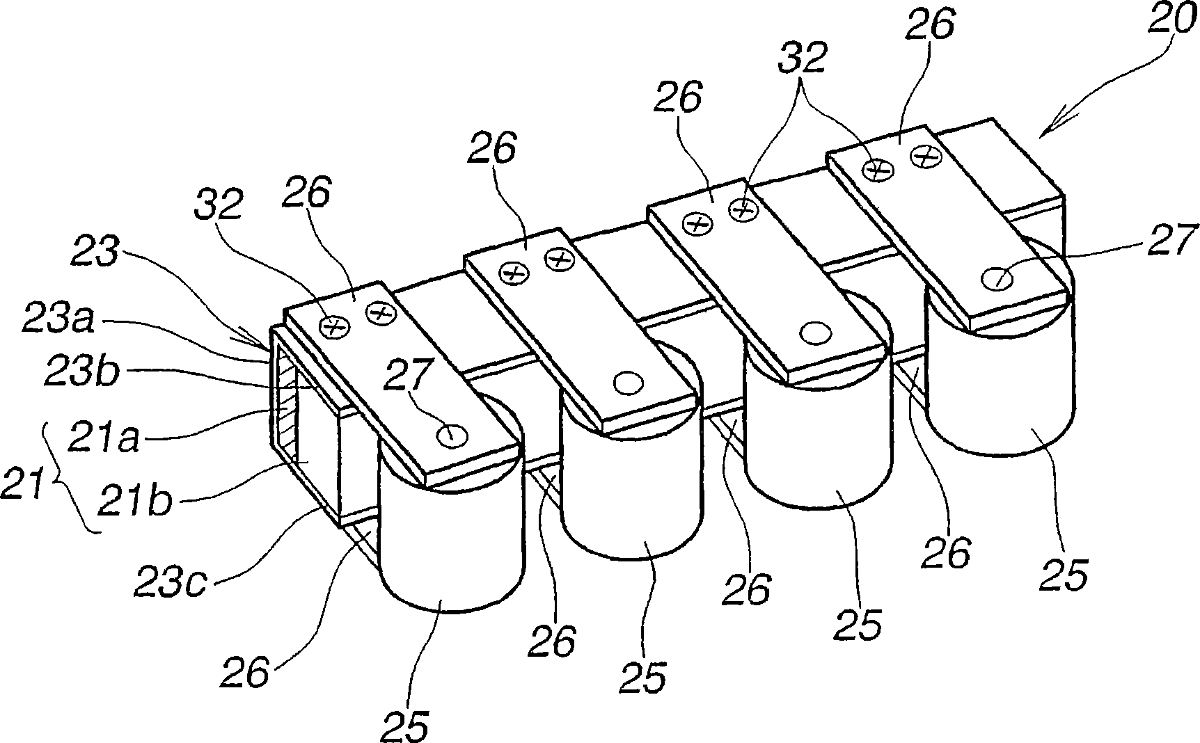
[0025] figure 1 , figure 2 and image 3 A linear motor driving device 10 and a driving section 20 according to a first embodiment of the present invention are shown. The driving device 10 of the first embodiment is composed of a rail 11 , a base body 12 movably mounted on the rail 11 , and left and right driving portions 20 , 20 provided on the base body 12 .

[0026] The base body 12 is U-shaped in section and has left and right leg portions 12a, 12a, and the base body 12 surrounds the top surface 11a and the side surfaces 11b, 11c of the rail 11, and applies a load to the rail through a plurality of rod bearings 13. 11 on the top surface 11a. The leg portions 12a, 12a of the base body 12 have supporting holes 14, 14 for supporting the driving portions 20, 20. The supporting holes 14 , 14 have open sides facing the side surfaces 11 b , 11 c of the rail, and are formed in the lengthwise direction of the base body 12 . The support hole 14 is composed of a first support ho...


PUM


Abstract

This invention relates to a drive device of an ultrasonic linear motor having a rail (11, 42) and a base body (12, 44) and driving parts (20, 50) interposed between rail and base body. The base body is moved in a straight line with respect to the length direction of the rail by the driving parts. The driving parts are provided on left and right leg parts (12a, 44a) of the base body, and the load of the base body acts almost not at all on the driving part. The driving parts have ultrasonic vibrators (21,52) and rollers (25, 51) rotationally driven by the ultrasonic vibrators. The rollers are urged by urging means (22, 53) toward and into contact with guiding side faces (llb, 11c, 42b, 42c) of the rail, driving forces generated by the driving parts act on the guiding side faces of the rail, and the base body moves in the length direction of the rail.

Description

technical field [0001] The present invention relates to an ultrasonic linear motor driving device, wherein a rail and a base body relatively move in the length direction by using the vibration of an ultrasonic vibrator as a driving source. Background technique [0002] This ultrasonic linear motor is composed of a base body having a piezoelectric device as a drive source at its center and a sliding member at its end, and a rail that supports the sliding member of this base body. An ultrasonic linear motor is disclosed in JP-A-6-6989 in which a sliding part of a base body abuts against a rail and the base body moves relative to the rail. The ultrasonic linear motor described in this publication will now be described with reference to FIG. 10 . [0003] The ultrasonic linear motor shown in FIG. 10 is composed of a rail 101; a base body 103 made of an elastic material and provided on the rail 101; piezoelectric devices 104, 104 mounted on the top of the base body 103 at predet...

Claims


Application Information

Patent Timeline
Patent Type & Authority Applications(China)
IPC IPC(8): H01L41/09H02N2/00
CPCH02N2/026
Inventor 市川茂须部佑一村上英治
Owner HONDA MOTOR CO LTD
Why Eureka
Try Eureka