
Gear cutting machine having a device for chamfering / deburring the edges of a work piece

A technology of gear cutting machine, oblique cutting, applied in the direction of gear cutting machine, components with teeth, gear tooth manufacturing device, etc.

Inactive Publication Date: 2007-02-14
THE GLEASON WORKS
View PDF3 Cites 13 Cited by
  • Summary
  • Abstract
  • Description
  • Claims
  • Application Information

AI Technical Summary

Problems solved by technology

this requires high effort

Method used


Image

  • Gear cutting machine having a device for chamfering / deburring the edges of a work piece
  • Gear cutting machine having a device for chamfering / deburring the edges of a work piece
  • Gear cutting machine having a device for chamfering / deburring the edges of a work piece

Examples


Embodiment Construction

[0011] specific implementation

[0012] The present invention has been described in detail by describing the preferred embodiment of the invention by way of example only.

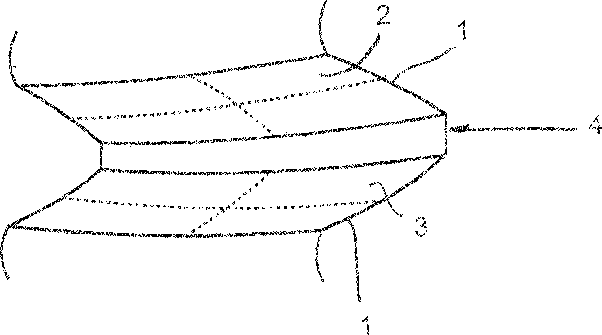
[0013] The device described below is used to chamfer and / or trim the sides of a bevel gear 2, 3 ( image 3 ) and back 4 ( image 3 indistinct) between the edge 1. The device can also be used to machine the area of ​​the edge 1 where the transition of the sides 2, 3 can be rounded towards the top (preferably tip cone angle) and / or the root (top and / or root rounding) .

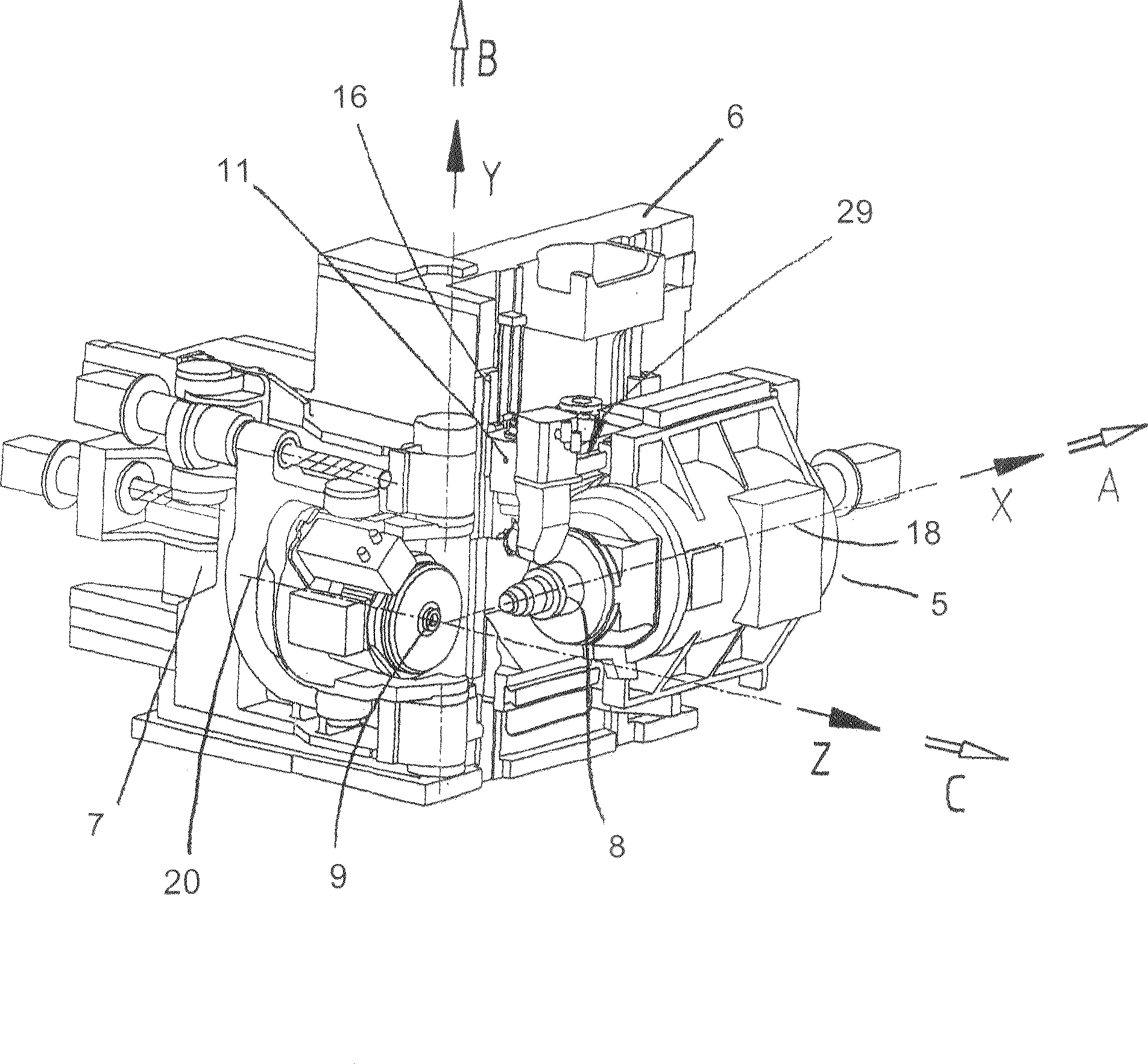
[0014] figure 1 Shown is a machine, such as that shown in U.S. Patent No. 6,712,566 to Stadtfeld et al., having features disposed on the machine, preferably on a stationary column or frame 6 of the machine, for mitering and / or Trimming device. The machine is a bevel gear cutting machine and has a workpiece holder 5 movable in the X direction (direction 18 of the axis of rotation of the workpiece). Furthermore, the workpiece support 5 i...


PUM


Abstract

A gear cutting machine wherein a chamfer / deburr device and tool are fastened to a fixed component of the gear cutting machine. In this way, it is possible to adjust the chamfering / deburring tool into the working position in a simple and dependable manner to remove the edges from a gear. The device preferably has a linear track as well as a pivot axis, which can position the tool into the optimum position for the chamfering and / or deburring of the gear.

Description

[0001] This application claims priority from German utility model application DE 202005011790.0 filed on 22.07.2005. technical field [0002] The invention relates to a gear cutting machine, in particular a bevel gear cutting machine, with a device for chamfering and / or bevelling the edge between the side and the back, in particular at the outer tooth ends of the gears produced by the gear cutting machine. Background technique [0003] With helical cut bevel gears, the flanks and backs of the teeth meet at a specific angle. The angle is acute where the concave side transitions into the back, ie the tooth that is not visible on the gullet. At this point, particularly large burrs are produced during machining. This burr must be eliminated. In many cases it is particularly desirable not only to eliminate burrs but also to provide a bevel. For gears with this type of bevel, the risk of injury during transport and installation is lower compared to sharp edges, moreover, imperm...

Claims


Application Information

Patent Timeline
Patent Type & Authority Applications(China)
IPC IPC(8): B23F19/10B23F9/10B23F23/12
CPCB23F9/10Y10T409/101113B23F23/12B23F19/10Y10T409/106201Y10T409/108586B23F5/24B23F19/00B23F1/06
Inventor K·培弗M·非利平
Owner THE GLEASON WORKS
Learn More