Deburring blade, device for mounting of deburring blades and bevel gear cutting machine for chamfering and/or deburring a bevel gear

a technology of bevel gear and deburring blade, which is applied in the direction of gear teeth, gear-teeth manufacturing apparatus, manufacturing tools, etc., can solve the problems of limited cutting speed of hss steel, not all bevel gears can be deburred on the gear-cutting machine with an impact tooth drill, etc., and achieves the effect of reducing processing time, reducing processing costs, and reducing processing costs

Active Publication Date: 2008-10-07
KLINGELNBERG AG
View PDF17 Cites 13 Cited by
  • Summary
  • Abstract
  • Description
  • Claims
  • Application Information

AI Technical Summary

Benefits of technology

[0016]It is an advantage of the invention that an appropriate bevel gear cutting machine is flexibly applicable. It can be reequipped depending upon need for continuous deburring of most diverse kinds by pinion gears. In addition the use of carbide blade inserts offers a larger freedom in the design of the edges of these blade inserts. The handling of the device according to the invention is particularly simple.
[0017]The essential advantages of the invention consist in that with the axis (numerical control axis), numerically controllable by means of a programmable control, almost any arbitrarily shaped bevel gear profile edges can be reached by the edges of the deburring blade inserts. Thus also w...

Problems solved by technology

Because of the large danger of injury, but also because of the danger of the full hardening when annealing the bevel gears these edges frequently are broken by a chamfer.
The crucial disadvantage is however that not all bevel gears can be deburred on their gear-cutting machine with an impact tooth drill.
As a further disadvantage is regarded that special impact tooth drills must be used.
It is a disadvantage of this principle that the cutting speed of the HSS steels is limited.
Thus the time that expires during the transferring into the change position is normally not sufficient, in order to...

Method used


Image

  • Deburring blade, device for mounting of deburring blades and bevel gear cutting machine for chamfering and/or deburring a bevel gear
  • Deburring blade, device for mounting of deburring blades and bevel gear cutting machine for chamfering and/or deburring a bevel gear
  • Deburring blade, device for mounting of deburring blades and bevel gear cutting machine for chamfering and/or deburring a bevel gear

Examples


Embodiment Construction

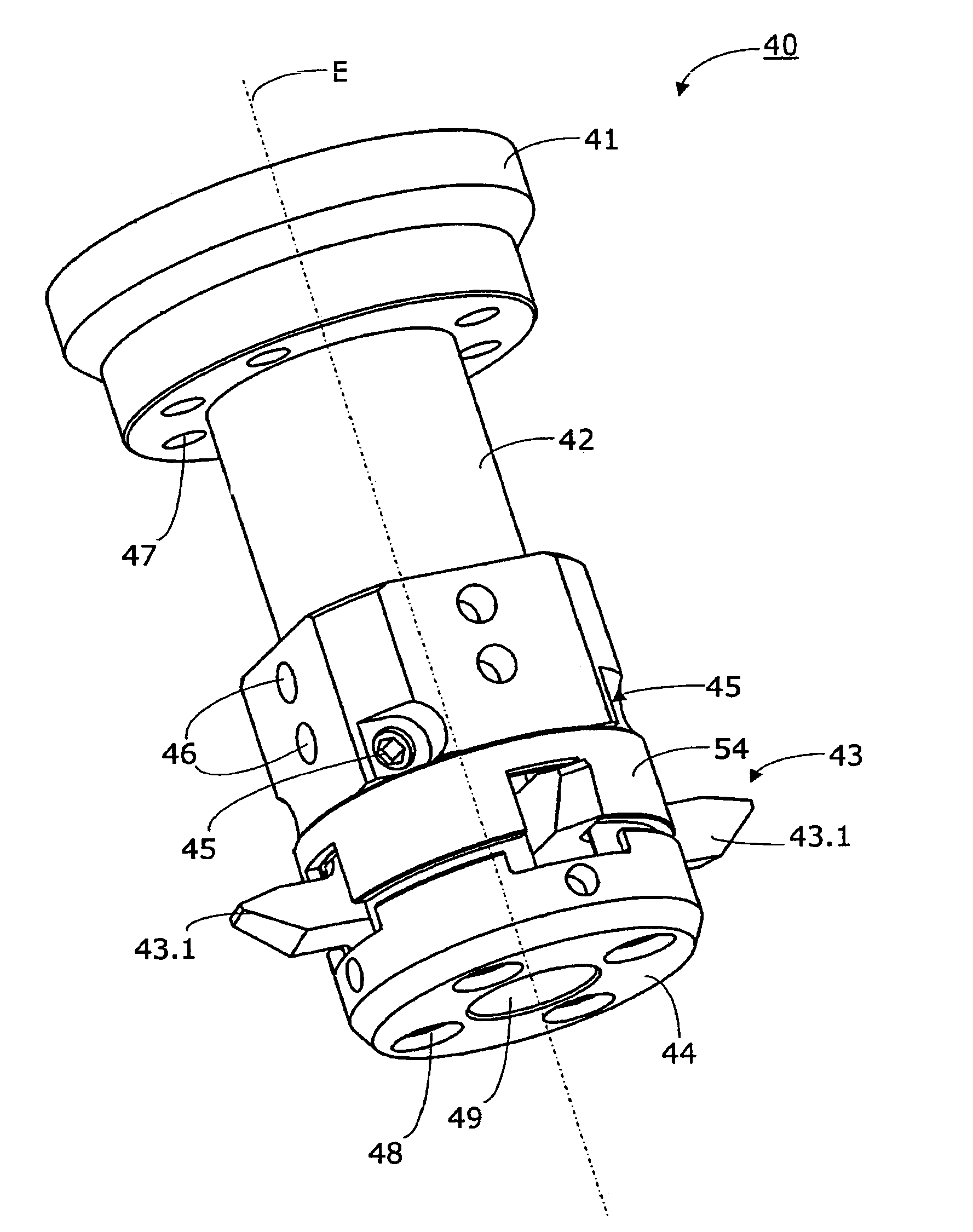
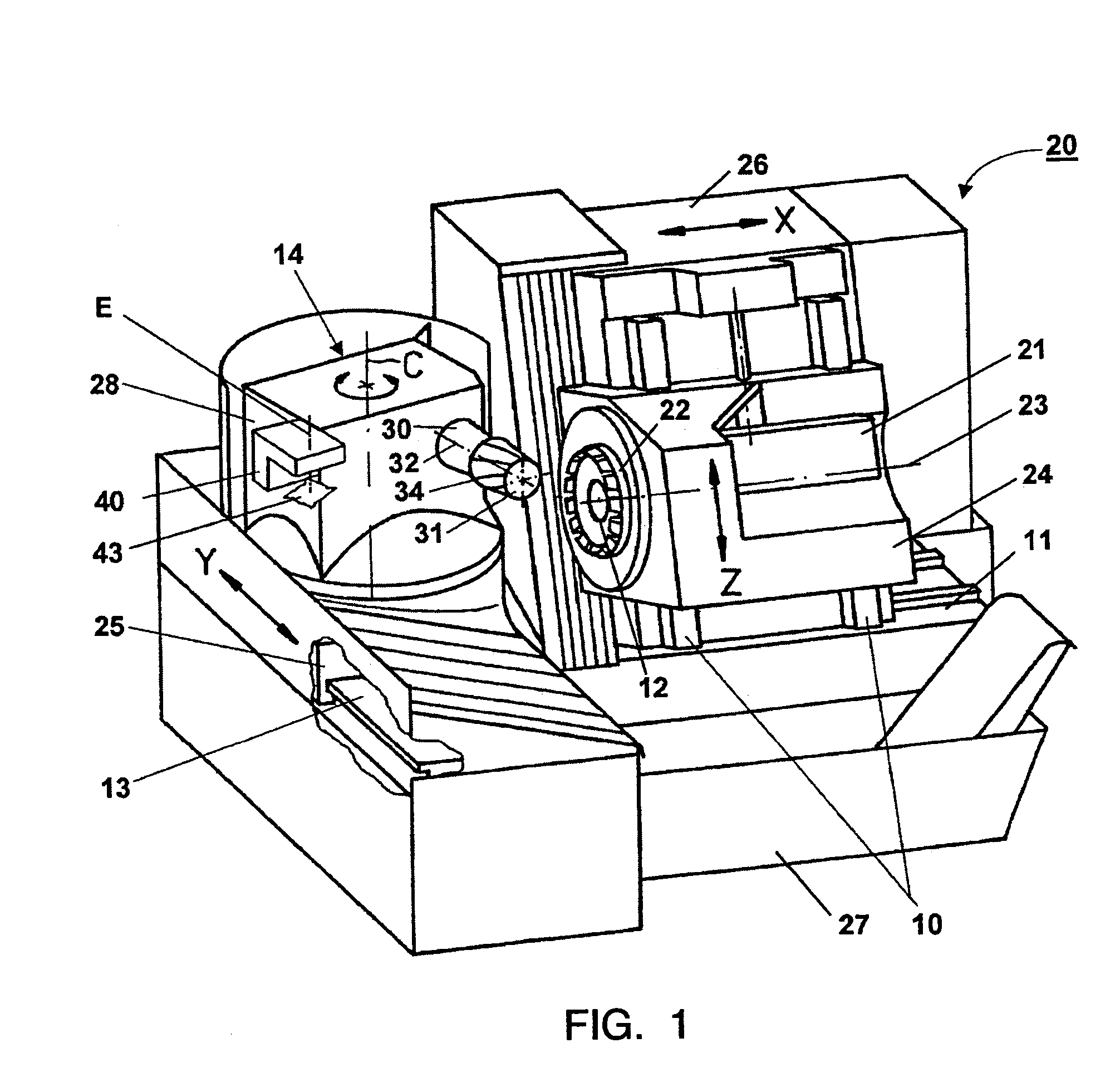
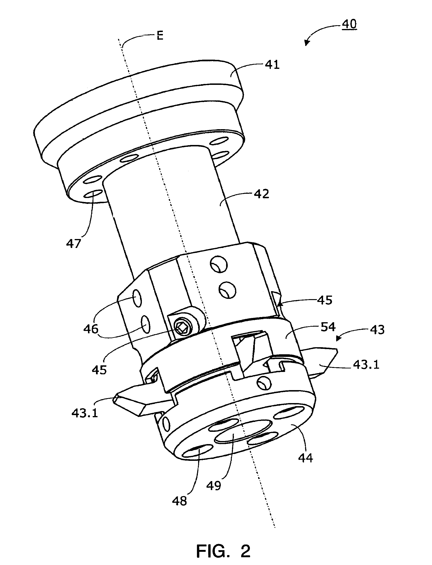
[0026]FIG. 1 shows the basic structure of a first CNC machine 20, according to the invention, for manufacturing helical bevel gears 31 in perspective representation. Such a machine 20 can be laid out or re-equipped according to the invention; in order to make possible a deburring or a chamfering of the bevel gear 31 by means of special deburring blade inserts 43.1 (see FIG. 2), which are part of a deburring blade head 43 being movable via a setting device 40.

[0027]The CNC machine 20 can be built-up as follows. On a machine bed 21 a machine housing 26 is horizontally and linearly guided along a straight axis of coordinates X (1st axis). A first carriage 24 is displaceable in its height by means of a jackscrew actuator 21 on a guidance 10, which is mounted on a side face of the machine housing 26, along a straight Z axis of coordinates (2nd axis). On the machine bed 11 a workpiece spindle carrier 14 is horizontally and linearly guided along a straight Y axis of coordinates (3rd axis),...


PUM

PropertyMeasurementUnit
Areaaaaaaaaaaa

Abstract

Bevel gear cutting machine for chamfering and/or deburring edges on the teeth of a bevel gear. The gear-cutting machine comprises a workpiece spindle, which receives the bevel gear coaxially of a spindle axis. Furthermore, a deburring spindle is provided for the receiving of a deburring tool and several numerically controllable axes are given. A deburring blade head with several blade cutter-like blade inserts serves as deburring tool, whereby the blade inserts are insertable in recesses of the deburring blade head essentially radially oriented to a deburring spindle axis (E) and comprise edges for chamfering and/or deburring.

Description

CROSS REFERENCE TO RELATED APPLICATIONS[0001]The priority of European Patent Application DE 20 2004 008 263 of May 19, 2004 is claimed, and the disclosure of the European Patent Application is incorporated by reference.FIELD OF THE INVENTION [0002]The present invention concerns gear-cutting machines and a deburring and / or a chamfering of the tooth edges of bevel gears in the continuous procedure.BACKGROUND OF THE INVENTION[0003]When manufacturing bevel gears a burr emerges at the outer tooth end due to the cutting processing, and in particular mainly at the concave flanks, because this flank forms a relatively pointed angle with the back surface of the bevel gear tooth. If one would remove the burr at this location only, a very sharp profile edge would remain. Because of the large danger of injury, but also because of the danger of the full hardening when annealing the bevel gears these edges frequently are broken by a chamfer. If this angle is not so pointed, because the bevel gear...

Claims


Application Information

Patent Timeline
IPC IPC(8): B23F19/10B23C5/10B23C5/20B23C5/22B23F21/12B23Q1/48B23Q1/62
CPCB23C5/22B23F19/102B23Q1/4852B23Q1/621Y10T409/106042Y10T409/104293Y10T407/1745Y10T409/103975Y10T409/10795Y10T409/108904Y10T409/101113B23F19/10B23F5/24
Inventor RIBBECK, KARL-MARTIN
Owner KLINGELNBERG AG
Why Eureka
Try Eureka