Bevel gear cutting machine for chamfering and/or deburring edges on the teeth of a bevel gear

a technology of bevel gear and cutting machine, which is applied in the direction of gear teeth, belt/chain/gearing, gear elements, etc., can solve the problems of inability to chamfer the outer tooth ends of slender shaft pinions, frequent broken edges, and inability to accept additional workpiece clamping

Inactive Publication Date: 2005-09-22
KLINGELNBERG AG
View PDF2 Cites 14 Cited by
  • Summary
  • Abstract
  • Description
  • Claims
  • Application Information

AI Technical Summary

Problems solved by technology

Because of the great danger of injury, but also because of harmful deformations when hardening the bevel gears, these edges are frequently broken by a chamfer.
In these devices, the disadvantage of additional workpiece clamping is accepted in order to have more space available in proximity to the workpiece than in a gear cutting machine, because then the deburring tools may be set more flexibly and easily to the particular workpiece dimensions.
It is disadvantageous in this case that the milling cutters must be aligned to one another and each milling cutter requires a special profiled shape for its cutting edges, which must be tailored to the particular bevel gear to be deburred.
In addition to the disadvantages which are connected with a separate deburring device, in this device, in spite of the great mechanical engineering complexity, the outer tooth ends of slender shaft pinions cannot be chamfered.
The decisive disadvantage, however, is that not all bevel gears may be deburred on their gear cutting machine using a fly-milling cutter.
A further disadvantage is that special fly-milling cutters must be used.
A gear cutting machine, in which a tool referred to as a planing tool, which is attached to a pneumatically-operated piston

Method used


Image

  • Bevel gear cutting machine for chamfering and/or deburring edges on the teeth of a bevel gear
  • Bevel gear cutting machine for chamfering and/or deburring edges on the teeth of a bevel gear
  • Bevel gear cutting machine for chamfering and/or deburring edges on the teeth of a bevel gear

Examples


Embodiment Construction

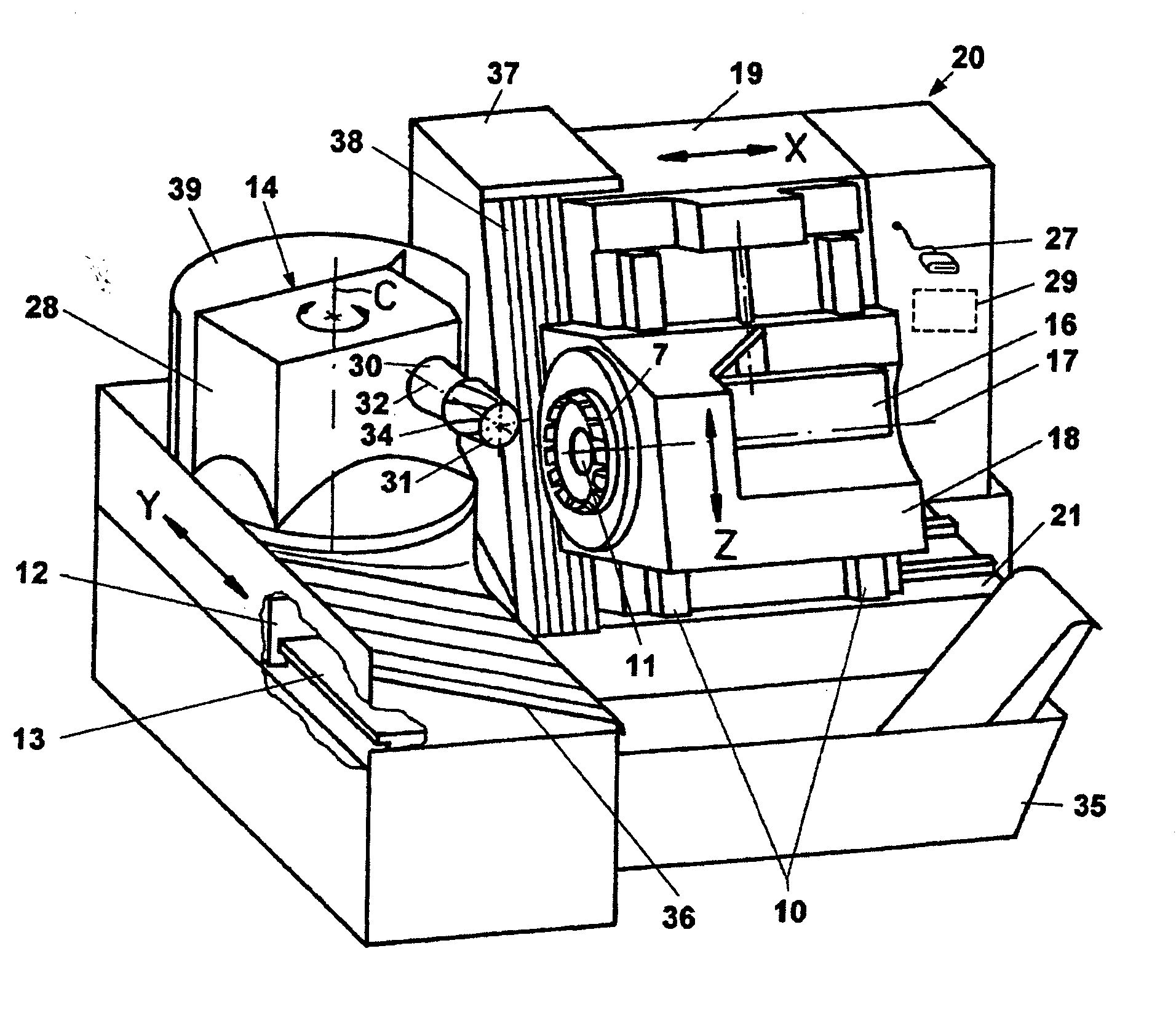
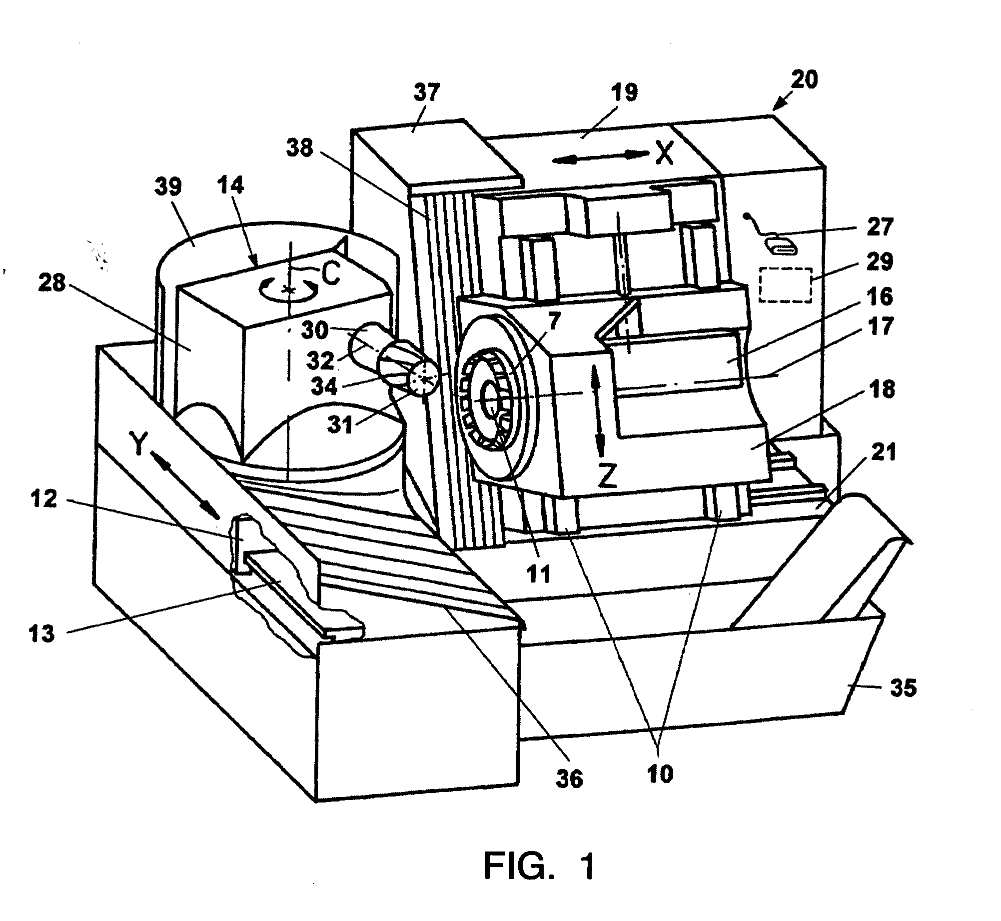
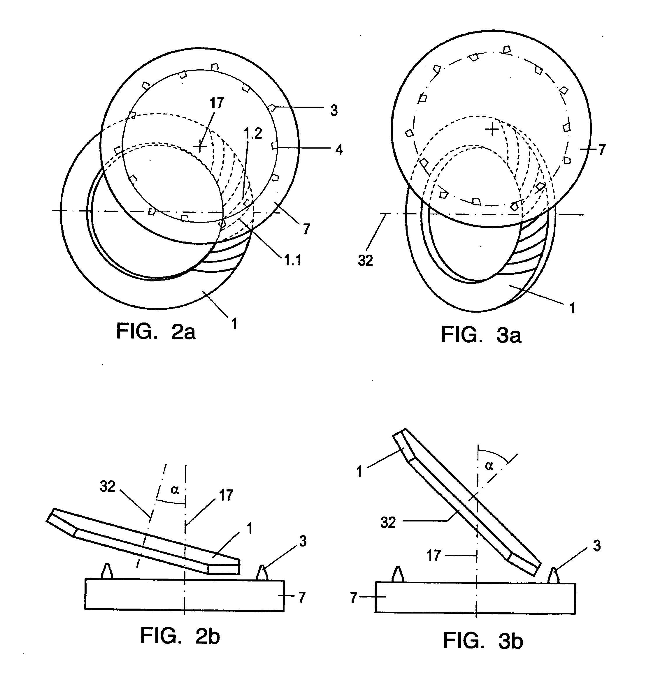
[0022] A possible embodiment of the present invention will be described in connection with FIGS. 1, 2, and 3. A bevel gear pinion is machined in FIG. 1, while in contrast a ring gear is machined in FIGS. 2 and 3.

[0023]FIG. 1 shows a perspective illustration of the basic construction of a CNC machine 20 for manufacturing spiral-toothed bevel gears 31. Such a machine 20 may be designed or retooled according to the present invention in order to allow deburring or chamfering of the bevel gear 31 using the same bar blades which are also used when manufacturing the teeth of the bevel gear 31.

[0024] The CNC machine 20 may be constructed as follows. A machine housing 19 is guided horizontally and linearly along a linear coordinate axis X (first axis) on a machine bed 21. A first carriage 18 may travel in height on a guide 10, which is attached to a side face of the machine housing 19, along a linear coordinate axis Z (second axis) using a spindle drive 16. A workpiece spindle support 14 h...


PUM

PropertyMeasurementUnit
Angleaaaaaaaaaa
Shapeaaaaaaaaaa

Abstract

A bevel gear cutting machine, which is designed for, among other things, chamfering and/or deburring edges on the teeth of a bevel gear. The gear cutting machine has a workpiece spindle which receives the bevel gear coaxially. A carriage is provided, which receives a plate-shaped cutter head having multiple bar blades. The gear cutting machine has multiple numerically controllable axes, which are activatable via a programmable controller, one of the axes forming a workpiece spindle axis of the workpiece spindle. Another axis is used as the tool spindle axis of the plate-shaped cutter head. The numerically controllable axes are implemented and positioned so that by adjusting at least one of the axes, the workpiece spindle, together with the bevel gear, may be inclined in relation to the cutter head in such a way that the bar blades, while the workpiece spindle rotates around the workpiece spindle axis and the cutter head rotates around the tool spindle axis simultaneously, plunge one after another into tooth intermediate spaces of neighboring teeth and execute a chamfering or deburring motion in relation to the edge.

Description

[0001] The present invention relates to gear cutting machines and the deburring and / or chamfering of the tooth edges of bevel gears. BACKGROUND INFORMATION [0002] When manufacturing spiral-toothed bevel gears, the tooth gaps are predominantly machined out from the small to the large diameter of the gear body using a cutter head. A burr arises at the outer tooth end in this case through the machining, predominantly on the concave flank, because this flank typically forms an acute angle with the rear face of the bevel gear tooth. If one merely removed the burr at this point, a very sharp profiled edge would remain. Because of the great danger of injury, but also because of harmful deformations when hardening the bevel gears, these edges are frequently broken by a chamfer. If this angle is not so acute, because the bevel gear has a small spiral angle, for example, it is sufficient to deburr the edge. [0003] Devices which were developed for conventional mechanical bevel gear cutting mac...

Claims


Application Information

Patent Timeline
IPC IPC(8): B23F9/10B23F9/14B23F19/10
CPCB23F9/10B23F19/102Y10T409/101113Y10T409/104134Y10T409/103975B23F19/10
Inventor MULLER, HARTMUTHRIBBECK, KARL-MARTIN
Owner KLINGELNBERG AG
Why Eureka
Try Eureka