Radio video recording home anti-theft apparatus
An anti-theft device and video recording technology, applied in anti-theft alarms, instruments, alarms, etc., can solve the problems of easy damage, complicated operation, expensive price, etc., and achieve the effect of improving the anti-theft effect
- Summary
- Abstract
- Description
- Claims
- Application Information
AI Technical Summary
Problems solved by technology
Method used
Image

Examples
Embodiment Construction
[0009] The present invention will be further described below in conjunction with the accompanying drawings and embodiments.
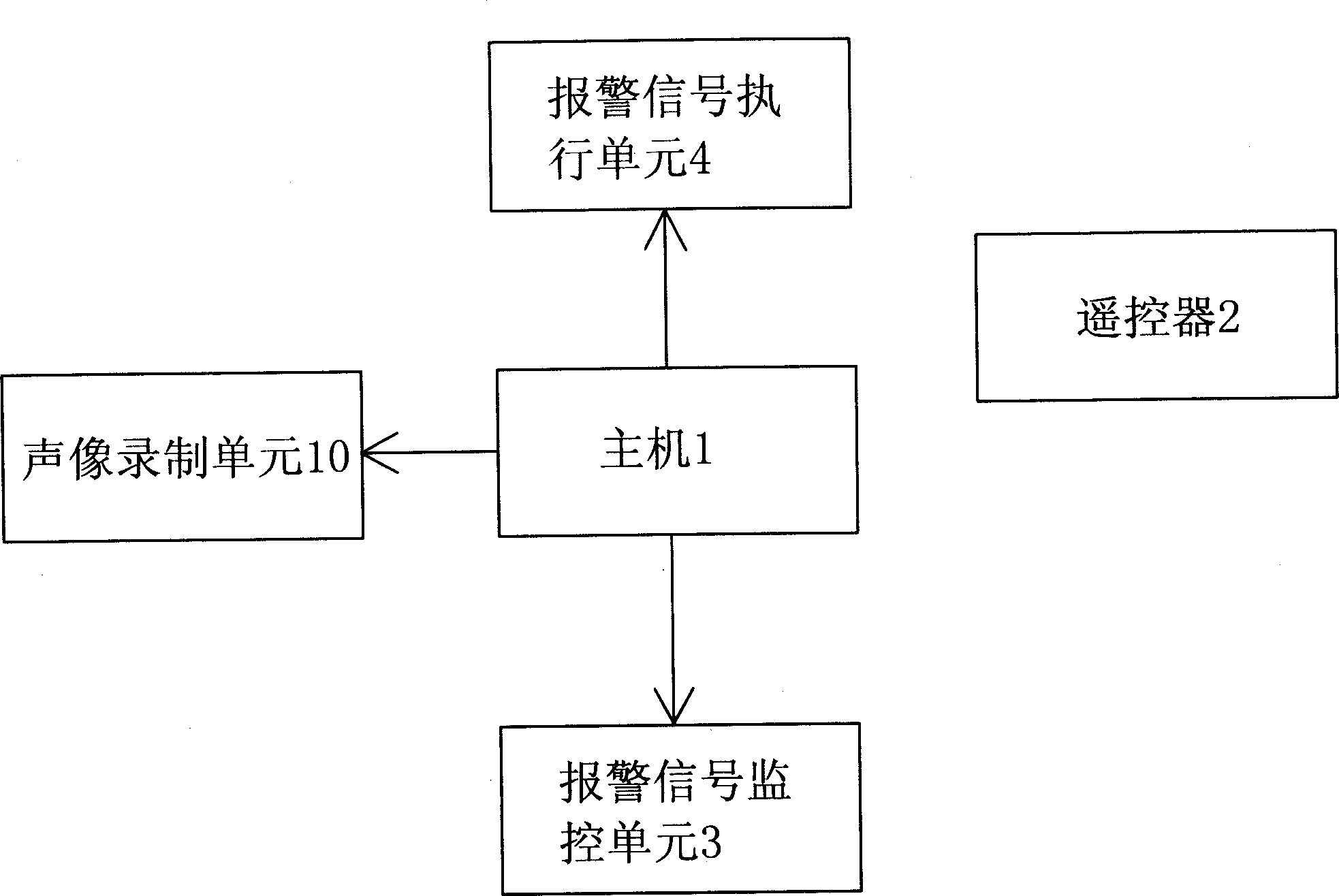
[0010] refer to figure 1 , a wireless video recorder home anti-theft device, including a host 1, a remote control 2, an alarm monitoring unit 3 and an alarm signal execution unit 4, characterized in that: the host 1 is also provided with an audio-visual recording unit 10.
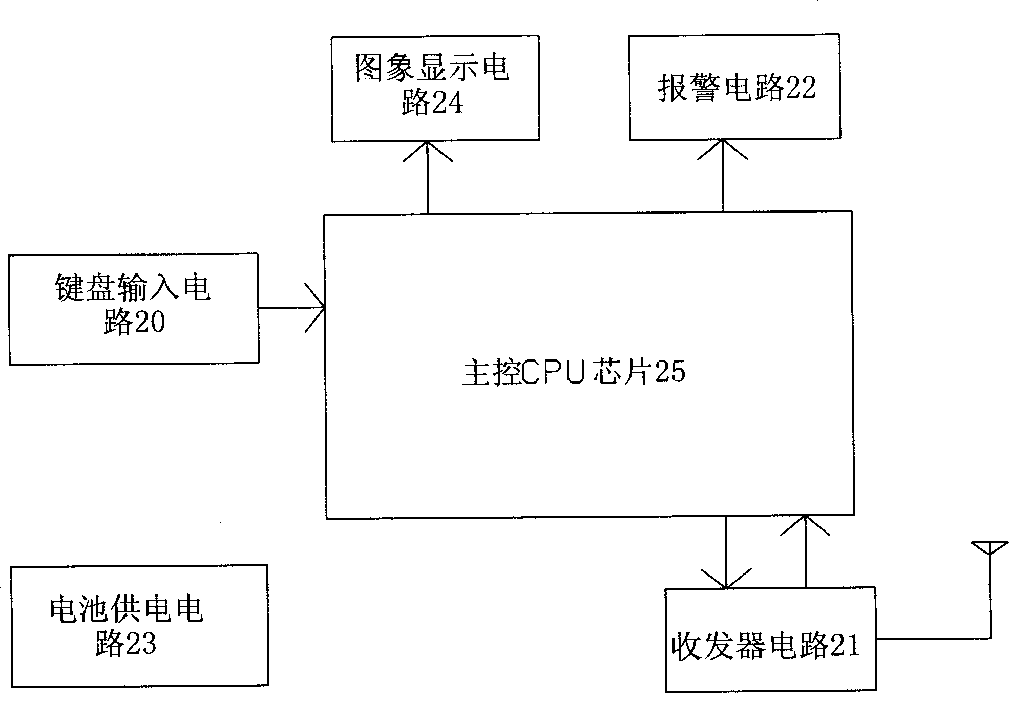
[0011] refer to figure 2 , the remote controller 2 of the present embodiment is mainly composed of a keyboard input circuit 20, a transceiver circuit 21, an alarm circuit 22, a battery power supply circuit 23, an image display circuit 24 and a main control CPU chip 25.
[0012] Among them, the keyboard input circuit 20 is used to input various control signals; the transceiver circuit 21 is used to realize the communication with the host computer 1; The instruction of 25 executes the alarm action, and the image display circuit 24 is used for displaying live images.
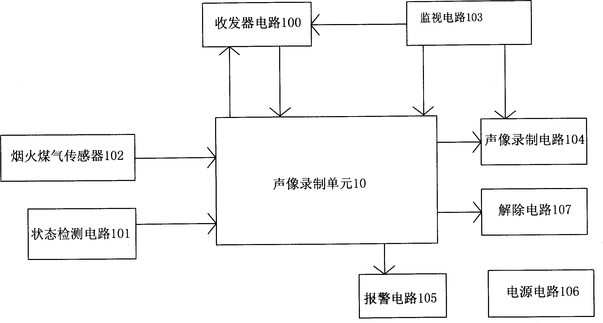
[0013] refer ...
PUM
 Abstract
Description
Claims
Application Information
 - Generate Ideas
- Intellectual Property
- Life Sciences
- Materials
- Tech Scout
- Unparalleled Data Quality
- Higher Quality Content
- 60% Fewer Hallucinations
Browse by: Latest US Patents, China's latest patents, Technical Efficacy Thesaurus, Application Domain, Technology Topic, Popular Technical Reports.
© 2025 PatSnap. All rights reserved.Legal|Privacy policy|Modern Slavery Act Transparency Statement|Sitemap|About US| Contact US: help@patsnap.com