Electronic equipment of having movable type antenna
An electronic device and antenna position technology, which is applied to antenna supports/installation devices, electrical equipment shells/cabinets/drawers, electrical components, etc., can solve the problems of increasing the production cost and mold opening time of the mold opening machine.
- Summary
- Abstract
- Description
- Claims
- Application Information
AI Technical Summary
Problems solved by technology
Method used
Image
Examples
Embodiment 1
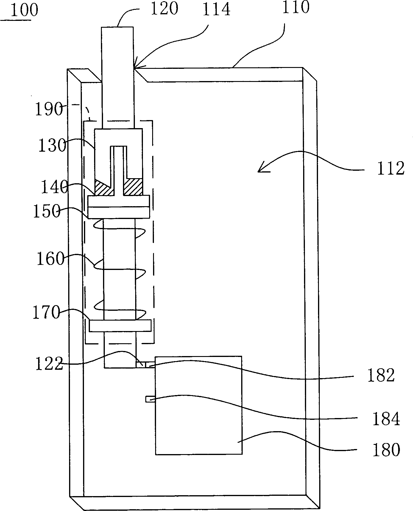
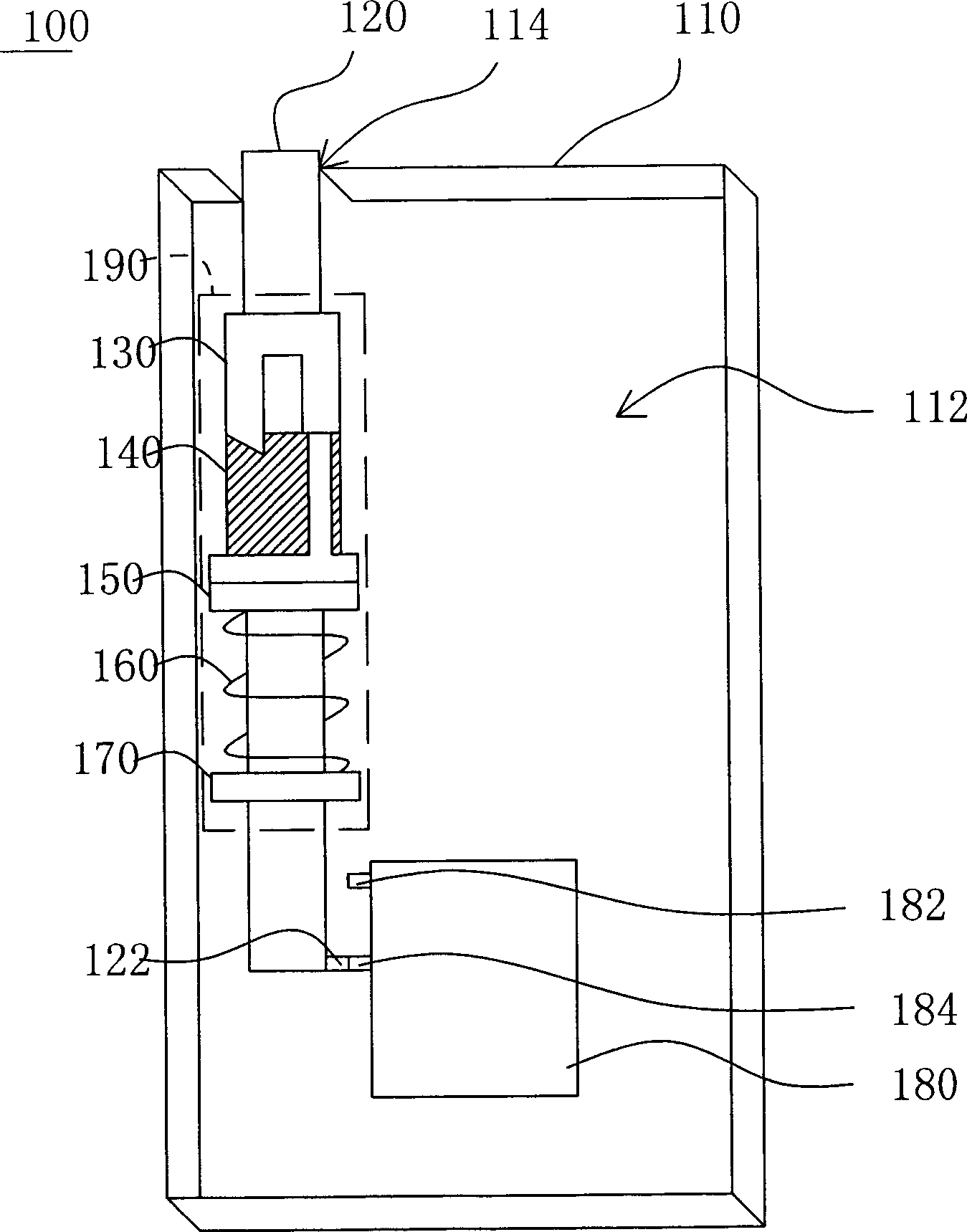
[0014] Please also refer to Figure 1A-1B , which are schematic diagrams of states when the antenna of the electronic device according to Embodiment 1 of the present invention is located at the protruding position and the storage position, respectively. exist Figure 1A-1B Among them, the electronic device 100 includes an antenna 120 and a casing 110 . The casing 110 has an opening 114 and an accommodating space 112 , and the antenna 120 can move back and forth between a protruding position and a receiving position in a manner of being able to enter and exit the opening 114 . When the antenna 120 protrudes out of the opening 114 , the antenna 120 is located at the protruding position to expose most of the structure, so that the antenna 120 is like a protruding antenna. When the antenna 120 is stored in the accommodating space 112 , the antenna 120 is located at the storage position, and a small part of the structure can be exposed, so that the antenna 120 is like a hidden ante...
Embodiment 2
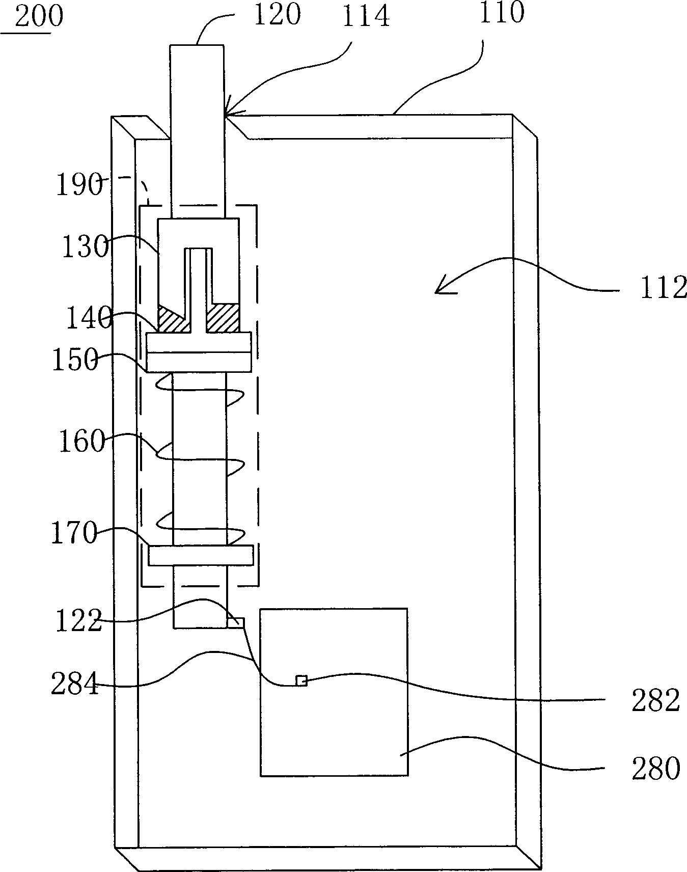
[0029]Please also refer to Figure 2A-2B , which are schematic diagrams of states when the antenna of the electronic device according to Embodiment 2 of the present invention is located at the protruding position and the storage position, respectively. The difference between the electronic device 200 of the present embodiment and the electronic device 100 of the first embodiment lies in the electrical contact method between the circuit board 280 and the antenna 120 . As for the other same components, the reference numerals will continue to be used and will not be repeated.
[0030] exist Figure 2A-2B Regardless of whether the antenna 120 is in the protruding position or the storage position, the third electrical terminal 122 of the antenna 120 is in electrical contact with a fourth electrical terminal 282 of the circuit board 280 through a conductor, such as a flexible wire 284 . Those with ordinary knowledge in the technical field of this embodiment can also understand that...
PUM
 Abstract
Description
Claims
Application Information
 - R&D
- Intellectual Property
- Life Sciences
- Materials
- Tech Scout
- Unparalleled Data Quality
- Higher Quality Content
- 60% Fewer Hallucinations
Browse by: Latest US Patents, China's latest patents, Technical Efficacy Thesaurus, Application Domain, Technology Topic, Popular Technical Reports.
© 2025 PatSnap. All rights reserved.Legal|Privacy policy|Modern Slavery Act Transparency Statement|Sitemap|About US| Contact US: help@patsnap.com


