Denture attachment and method for manufacturing the same

A manufacturing method and technology of accessories, applied in fasteners, medical science, dentistry, etc., can solve the problems of low productivity, difficult to realize automation, cumbersome work, etc., and achieve high durability, high magnetic adsorption, Good corrosion resistance

Inactive Publication Date: 2012-04-18
HITACHI METALS LTD
View PDF2 Cites 0 Cited by
  • Summary
  • Abstract
  • Description
  • Claims
  • Application Information

AI Technical Summary

Problems solved by technology

As a result, there is still the problem of forming welded parts that are inconsistent in the range and depth of the weld.
Moreover, because the work of pressing the small plate-shaped yoke 504 into the small cup-shaped yoke 501 requires precise control after all, not only is it difficult to automate, but also the productivity is not high because of the cumbersome workmanship.

Method used


Image

  • Denture attachment and method for manufacturing the same
  • Denture attachment and method for manufacturing the same
  • Denture attachment and method for manufacturing the same

Examples


Embodiment 1

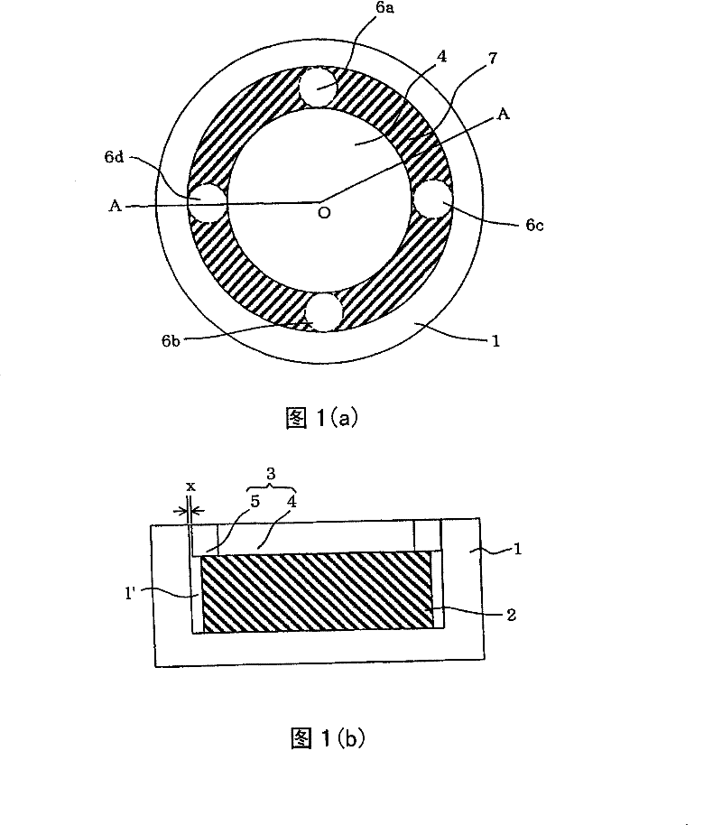
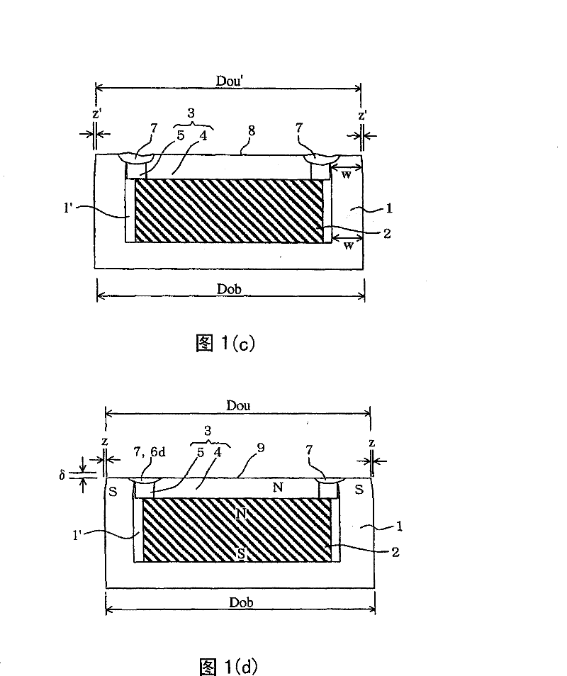
[0088] Cup yokes and seal plates with dimensions shown in Table 1 were used. This sealing plate is a cylindrical material that should be used as a sealing ring embedded in a round rod for a disc-shaped yoke. After drawing, it is cut into slices with a thickness of 0.2mm, and then heat-treated at 800°C in a reducing atmosphere. Then cool to room temperature. The seal plate obtained is obtained by lightly joining the seal ring on the outer periphery of the disc-shaped yoke. Assembled as shown in Figure 1(b), as shown in Table 2, along the circle with a diameter of 2.4mm (with the point O in Figure 1(a) as the center) at the same angular interval of 90°, passing through the 0.5mm spot diameter After the laser spot welding, it was temporarily fixed, and then the whole circumference was welded with a laser with a spot diameter of 0.5 mm along the circumference of the same diameter of 2.4 mm (Fig. 1(c)). As shown in Fig. 3(b), the diameter of the opening of the cup yoke 1 immediat...

Embodiment 2~6

[0092] Use the cup-shaped yoke and the sealing plate of the dimensions shown in Table 1 (the sealing plate is the same as that of Example 1, and the sealing ring is slightly joined to the outer periphery of the disc-shaped yoke), such as Figure 5 As shown in the assembly, as shown in Table 2 to cover the butt joint of cup yoke 21 and seal ring 25, along the circumference of diameter 2.6mm (in Figure 5 The point O of (a) is the center) The first spot welding is performed with a laser having a spot diameter of 0.2mm at the same angular interval of 90°, and the butt joint between the seal ring 25 and the plate-shaped yoke 24 is covered, along the diameter of 2.2mm the circumference of Figure 5 Point O in (a) is the center) and the second spot welding is performed at the same angular interval of 90° with a laser having a spot diameter of 0.2 mm to temporarily fix the sealing plate 23 to the cup yoke 21 . Next, along a circle with the same diameter of 2.6 mm as that of the firs...

Embodiment 7

[0094] As shown in Table 2, the denture attachment shown in Fig. 6 was produced in the same manner as in Example 2 except that the spot diameters of the laser beams for spot welding and circumferential welding were each set to 0.3 mm, and their characteristics were measured. . The measurement results are shown in Table 3.


PUM


Abstract

A denture attachment, comprises a permanent magnet, a cup-like yoke formed of a corrosive resistant soft magnetic material having a recessed part for storing the permanent magnet, and a seal plate fitted to the opening part of the recessed part of the yoke. The seal plate further comprises a plate-like yoke formed of the corrosive resistant soft magnetic material and a seal ring formed of a corrosive resistant non- magnetic material disposed on the outer periphery of the plate-like yoke. The denture attachment is characterized in that the seal plate is joined to the yoke by a plurality of spot welded parts in which at least a butted part between the yoke and the seal ring is fixed and at least one welding-all-around part formed to cover the butted part between the yoke and the seal ring and the butted part between the seal ring and the plate-like yoke so as to seal the permanent magnet.

Description

[0001] technology area [0002] The invention relates to a denture attachment for holding dentures by magnetic attraction force of a permanent magnet and a manufacturing method thereof. Background technique [0003] like Figure 24 and Figure 25 As shown, in Japanese Patent Application Laid-Open No. 4-227253, a denture 430 is disclosed, which has a permanent magnet 402 inside, and also has: a denture attachment 400 embedded in a denture bed 420; The soft magnetic armature (keeper) 423 provided on the root plate 422 in 421 is held on the root plate 422 under the magnetic attraction force of the permanent magnet 402 and the armature 423 . The denture attachment 400 has a structure in which a soft magnetic stainless steel sealing disc 414 and a non-magnetic stainless steel sealing ring 415 are arranged concentrically on the opening of the soft magnetic stainless steel cup yoke 401, and the sealing disc 414 The permanent magnet 402 is sealed after being welded with the sealing ...

Claims


Application Information

Patent Timeline
Patent Type & Authority Patents(China)
IPC IPC(8): A61C13/235A61C8/00
CPCA61C8/0081A61C13/235
Inventor 菊地亮
Owner HITACHI METALS LTD
Why Eureka
Try Eureka