Electroacoustic transducer

A technology of electro-acoustic transducers and magnetic materials, applied in the direction of sound-generating devices, instruments, sensors, etc., can solve the problems of increasing production costs and deterioration, and achieve the effects of increasing rear space, ensuring volume, and reducing airtightness

Inactive Publication Date: 2005-12-21
STAR MICRONICS
View PDF0 Cites 0 Cited by
  • Summary
  • Abstract
  • Description
  • Claims
  • Application Information

AI Technical Summary

Problems solved by technology

However, this method of fixing has concerns such as the adhesive deterior

Method used


Image

  • Electroacoustic transducer
  • Electroacoustic transducer
  • Electroacoustic transducer

Examples


Embodiment Construction

[0033] Embodiments of the present invention will now be described in detail with reference to the accompanying drawings.

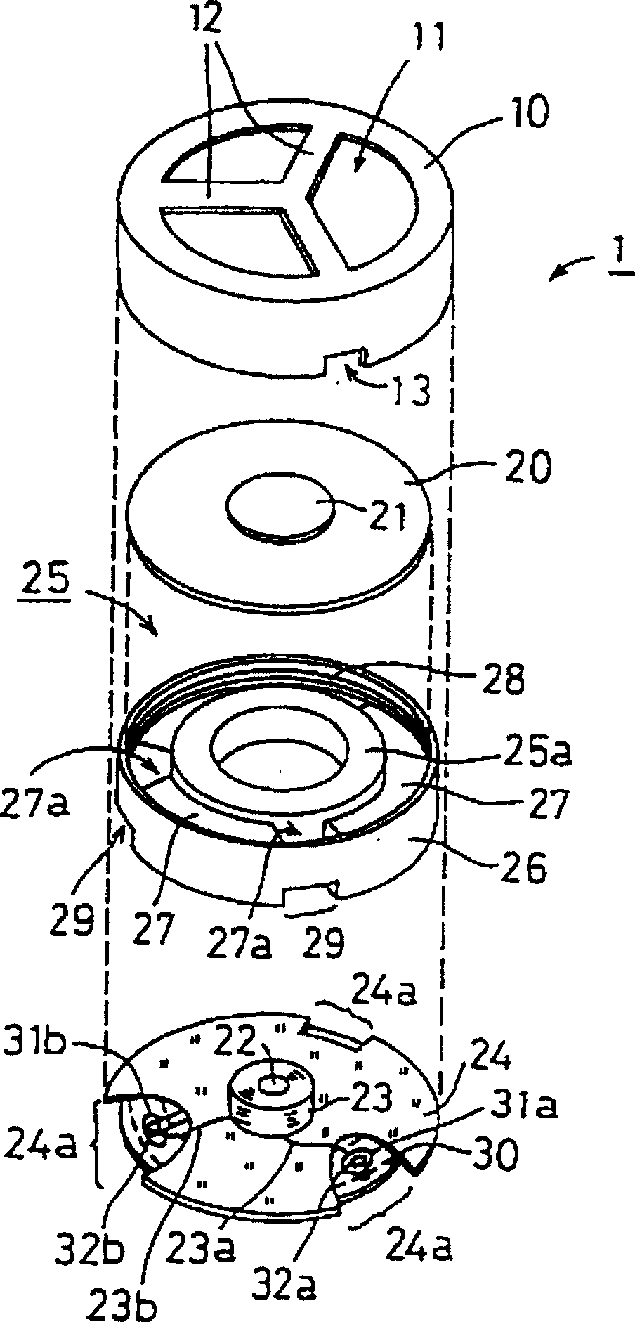
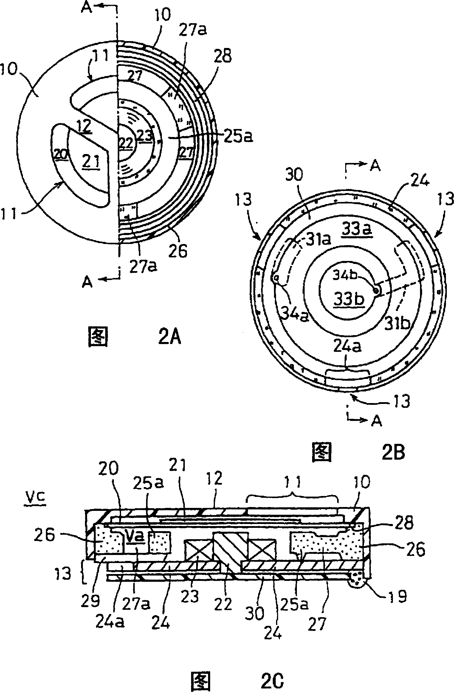
[0034] figure 1 To show an exploded perspective view of an embodiment of the present invention, FIG. 2A is a front view (left half) and a sectional view (right half) seen from the sound outlet 11, FIG. 2B is a bottom view, and FIG. 2C is a view along the view. The end view taken along line A-A of 2A.

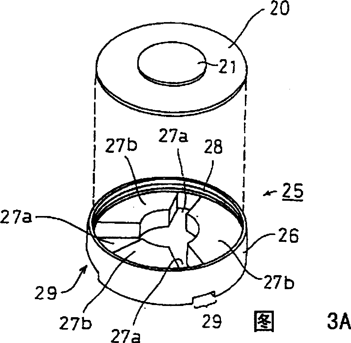
[0035] The electroacoustic transducer 1 is configured by placing a base 24, a magnetic core 22, a coil 23, a magnetic field generator 25 and a diaphragm 20 in a housing 10, and its overall shape is a flat cylinder . For example, the overall transducer size is approximately 12mm in diameter x 3mm in height.

[0036] The base 24 is shaped like a disk, and its cut portion 24a is formed along the circumference. In an embodiment, three cutting portions 24a are formed circumferentially at intervals of 120 degrees, wherein two cutting portions 24a form a U sha...


PUM


Abstract

The electroacoustic transducer (1) comprises a base (24) made of magnetic material; a magnetic core (22) made of magnetic material placed on the base; a diaphragm made of magnetic material (20); a magnetic field generator (25) that forms a magnetic circuit with the base (24), magnetic core (22) and diaphragm (20) and is used to provide a static magnetic field; and a coil that is arranged around the magnetic core (23) Used to provide an oscillating magnetic field to the magnetic circuit. The magnetic field generating body includes multiple rings, the surfaces of which are opposite to the diaphragm respectively have the same magnetic poles, and the multiple rings include ring magnets arranged to surround the coil and support rings arranged to surround the ring magnets.

Description

technical field [0001] The invention relates to an electroacoustic transducer for generating sound by electromagnetic sound conversion. Background technique [0002] Figure 10 is a perspective view showing an example of an electroacoustic transducer in the conventional art. The configuration of the electroacoustic transducer 90 is: a diaphragm 93 made of magnetic material, and a magnetic sheet 94 is fixed at the center; an electromagnetic coil (not shown) that provides an oscillating magnetic field to the diaphragm 93; the diaphragm 93 and the electromagnetic coil are placed The shell 91, and so on. Since the sound outlet 91b having a diameter larger than that of the magnetic sheet 94 is formed in the top plate 91a relative to the diaphragm 93, such a transducer is generally called an open electroacoustic transducer. [0003] When an electric oscillation signal is supplied to the electromagnetic coil, the diaphragm 93 oscillates by the oscillating magnetic field generated...

Claims


Application Information

Patent Timeline
IPC IPC(8): H04R11/02H04R9/00
CPCH04R9/00
Inventor 增田充宏曾根高裕
Owner STAR MICRONICS
Why Eureka
Try Eureka