Electrode catheter

An electrode catheter and electrode technology, used in catheters, medical science, surgery, etc., can solve problems such as the collapse of the injection tube lumen, damage to the fluid flow, interfere with the injection tube, etc., and achieve the effect of high strength

Active Publication Date: 2019-10-25
JAPAN LIFELINE CO LTD
View PDF9 Cites 1 Cited by
  • Summary
  • Abstract
  • Description
  • Claims
  • Application Information

AI Technical Summary

Problems solved by technology

[0009] In the electrode catheter described in Patent Document 2, when the rotating operation part is operated, the rotating operation part, operation cables, and lead wires may interfere with the infusion tube, or the infusion tube may be twisted, or the lumen of the infusion tube may collapse to impair the flow of liquid. sex

Method used


Image

  • Electrode catheter
  • Electrode catheter
  • Electrode catheter

Examples


no. 1 approach >

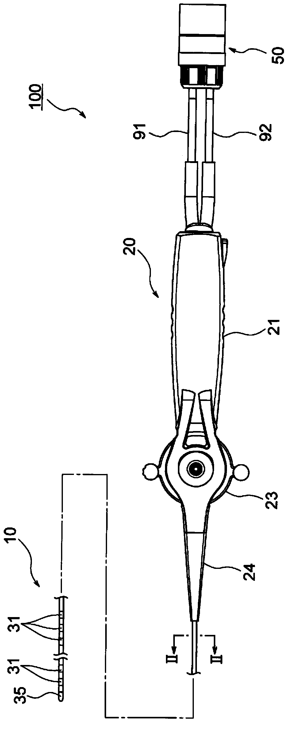
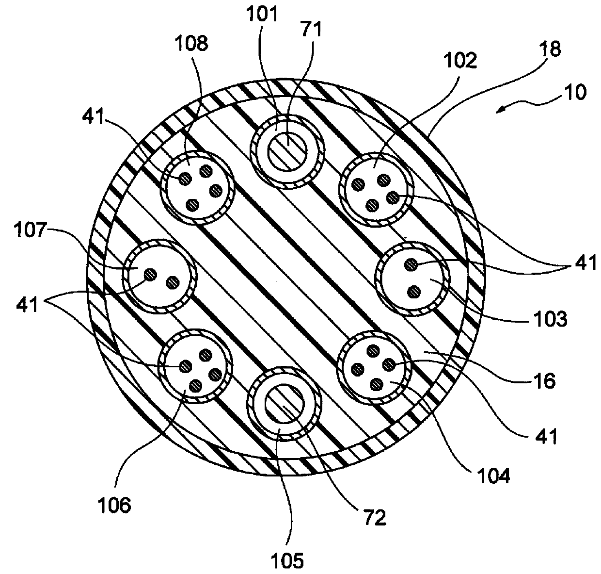
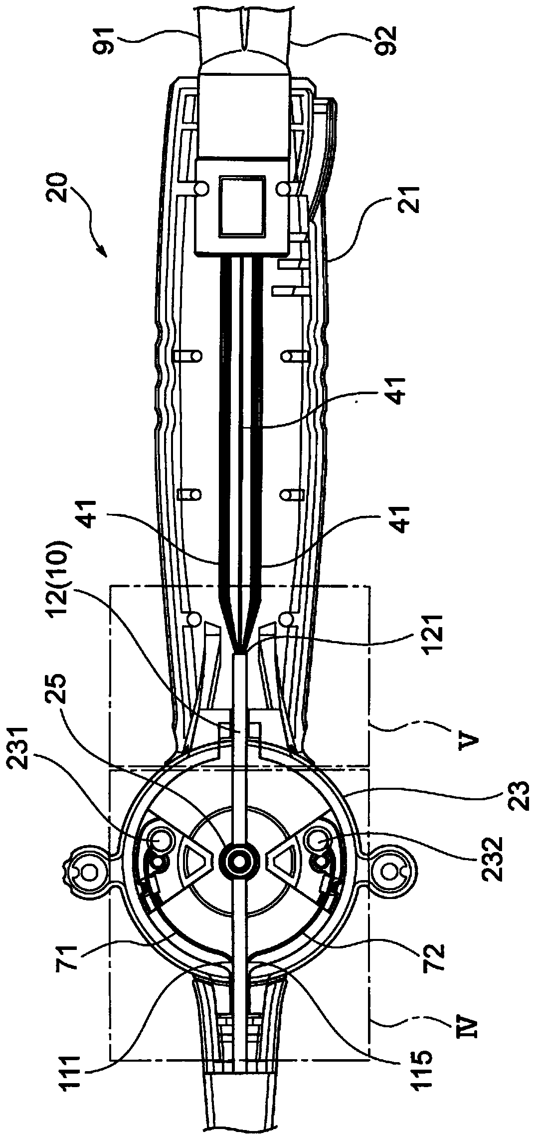
[0078] figure 1 ~ Figure 5 ( Figure 5A as well as Figure 5B The lead 100 of the present embodiment shown in ) is an lead for diagnosis or treatment of arrhythmia.

[0079] The electrode catheter 100 includes an insulating tube member 10 having a flexible portion at the distal end and eight lumens 101 to 108 arranged at equal angular intervals along the circumferential direction, and a handle 20 attached to the tube member The proximal end portion 12 of the tube member 10 has a handle body 21 and a rotary operation portion 23 provided with cable holders 231 and 232; figure 1 A part of the illustration is omitted); front-end chip 35, which is mounted on the front end of the tube member 10; 20 wires 41, whose respective front ends are connected to the 20 electrodes 31 and extend axially inside the tube member 10; electrode connection The device 50 is arranged on the proximal end side of the handle 20 and has a terminal (not shown) to which the proximal ends of the lead wires...

no. 2 approach >

[0127] Figure 6 to Figure 11 The illustrated lead 200 of the present embodiment is a lead lumen lead for diagnosis or treatment of arrhythmias.

[0128] This electrode catheter 200 includes: an insulating tube member 15 having a flexible portion at the distal end and forming a central lumen 150 serving as a lead lumen and eight sub-lumens 151 to 158 arranged at equal angular intervals around the central lumen 150 ; The handle 20 is attached to the proximal end portion 17 of the pipe member 15 and has a handle body 21 and a rotary operation portion 23 provided with cable fixing members 231 and 232; and 20 annular electrodes 31 attached to the pipe member 15. The periphery of the front end portion (at Image 6 The front end chip 37, which is mounted on the front end of the tube member 15; 20 wires 41, whose respective front ends are connected to 20 electrodes 31, extend along the axial direction inside the tube member 15; the electrodes The connector 50 is arranged on the pro...


PUM


Abstract

The purpose of the present invention is to provide an electrode catheter wherein when a rotation operation unit is operated, the rotation operation unit and an operation wire do not interfere with a lead, no abnormal noise is generated during operation, and the lead does not become damaged or broken even when the operation is repeated. This electrode catheter is provided with: a tube member (10);a handle (20) having a rotation operation unit (23); an electrode (31) mounted on the tube member (10); a lead (41); an electrode connector 50; and operation wires (71, 72). A base end part (12) of the tube member (10) is inserted into the handle (20) from the leading end thereof, and extends in the handle (20) beyond the rotation operation unit (23) towards the base end. Side holes (111, 115) areformed in the tube wall of the base end part (12) of the tube member (10). Base end parts of the operation wires (71, 72) extend to the outside of the tube member (10) through the side holes. The base ends of the operation wires (71, 72) are fixed to wire fasteners (231, 232).

Description

technical field [0001] The present invention relates to electrode catheters. Background technique [0002] In a conventional electrode catheter, an operation cable for deflecting the distal end, and a proximal end portion of a tube member in which the lead wire of the electrode extends, are inserted into the inside from the distal end side of the handle, and the operation cable and The lead wire extends from the base end of the tube member opened near the front end of the handle to the inside of the handle. [0003] Here, the base end of the operation cable is fixed to the cable fixing tool of the rotary plate (rotation operation part) for performing the tip deflection operation, and the base end part of the lead wire passes through the one side or the other side of the rotation operation part and is fixed on the cable holder. The inside of the handle extends, and the proximal end of the lead wire is connected to an electrode connector located on the proximal end side of th...

Claims


Application Information

Patent Timeline
Patent Type & Authority Applications(China)
IPC IPC(8): A61M25/092A61B18/14A61B5/296
CPCA61B5/6852A61B2018/1467A61B18/1492A61B2018/0091A61B34/71A61B2218/002A61B5/25A61B5/283A61B5/287A61B5/291A61B5/296A61B2562/0209
Inventor 桝田拓也
Owner JAPAN LIFELINE CO LTD
Why Eureka
Try Eureka