
A method for manufacture a wireless communication antenna

A wireless communication and manufacturing method technology, applied to antennas, loop antennas, antenna parts, etc., can solve the problem of thickening the overall thickness and achieve the effects of ensuring productivity, eliminating common processes, and efficient charging

Active Publication Date: 2019-01-08
SHENZHEN ACCOMTECH COMM ELECTRONICS CO LTD
View PDF10 Cites 2 Cited by
  • Summary
  • Abstract
  • Description
  • Claims
  • Application Information

AI Technical Summary

Problems solved by technology

[0028] However, the structure of the wireless antenna coil for a smart phone in the prior art document has a structure in which a heat dissipation layer 57a is coated on a heat dissipation film 57, and a heat conduction adhesive layer 57b is formed under the heat dissipation film 57 for bonding with other layers. There is a problem that the overall thickness becomes thicker due to the thickness of the heat dissipation film 57

Method used


Image

  • A method for manufacture a wireless communication antenna
  • A method for manufacture a wireless communication antenna
  • A method for manufacture a wireless communication antenna

Examples


Embodiment Construction

[0074] Referring to the accompanying drawings, the preferred embodiment of the method for manufacturing a wireless communication antenna of the present invention is described. There may be multiple embodiments. Through such an embodiment, the purpose, features and advantages of the present invention can be better understood.

[0075] Figure 8 is a process diagram showing a method for manufacturing a wireless communication antenna of the present invention, Figure 9a is a cross-sectional view showing a metal thin film, Figure 9b is a cross-sectional view for explaining each step of the method for manufacturing the wireless communication antenna according to the first embodiment of the present invention, Figure 9c It is a sectional view for explaining each step of the method of manufacturing the wireless communication antenna according to the second embodiment of the present invention. In the following description, the surface and the inside are distinguished from each othe...


PUM


Abstract

A method for manufacture a wireless communication antenna includes for a surface metal layer on one side surface of a flexible film, forming a surface metal layer on one side surface of that flexiblefilm, forming a surface metal lay on the surface metal layer, and forming a surface metal layer on the surface metal layer. S20, patterning the surface metal layer to form a helical antenna; Step S30,the metal is vacuum deposited on the other side surface of the flexible film to form an inner metal layer. The invention realizes better short-range wireless communication and also realizes heat dissipation of various components in the portable terminal.

Description

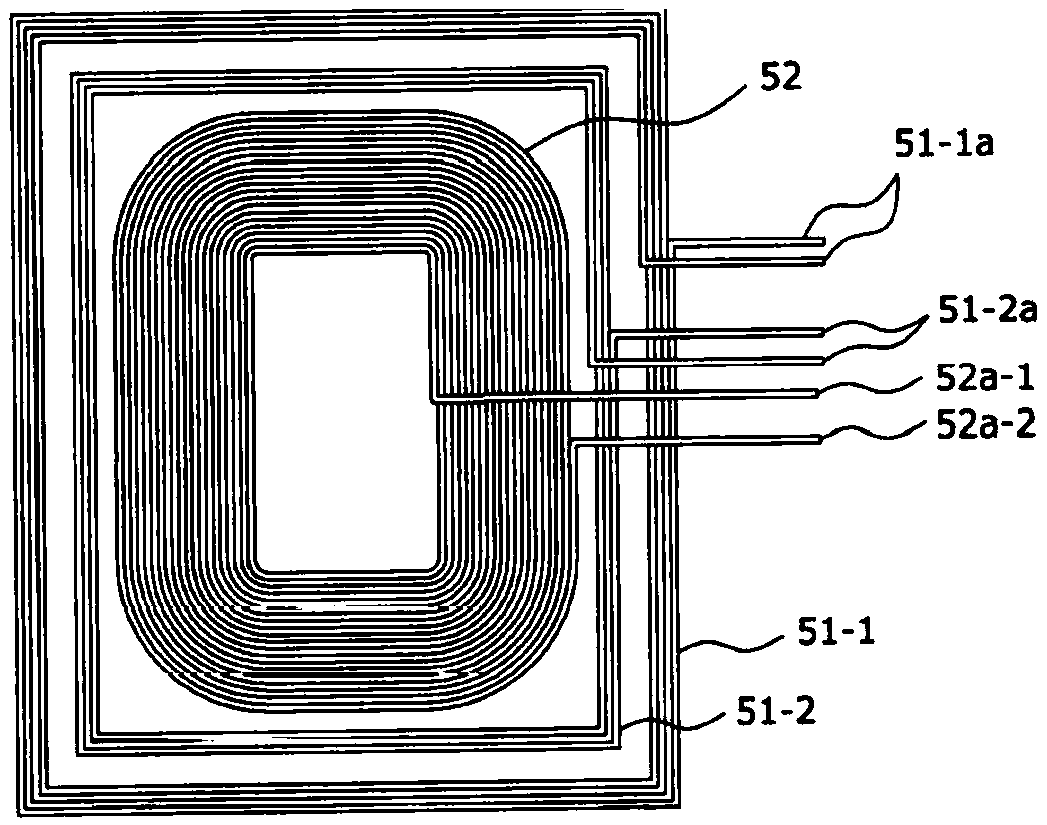
technical field [0001] The present invention relates to a method for manufacturing a wireless communication antenna. More specifically, it relates to a method for utilizing a pre-formed surface metal layer on one side of a flexible film. The inner metal layer is formed on the other side of the film, and the inner metal layer is formed simply and easily by vacuum deposition, which reduces the waste of metal during processing, and ensures easy workability, which can greatly improve the productivity of wireless communication antennas. Background technique [0002] In general, tablets and smartphones generate heat from the drive of multiple circuit components required for wireless communication and various calculations through power supply, and this heat acts as a major factor that shortens the life of the components. , requires a structure that dissipates heat as quickly as possible. [0003] figure 1 It is a figure which shows the Example of the antenna coil of the prior art...

Claims


Application Information

Patent Timeline
Patent Type & Authority Applications(China)
IPC IPC(8): H01Q1/38H01Q7/06H01Q1/00
CPCH01Q1/02H01Q1/38H01Q7/06H01Q1/44H01Q7/00C23C14/14C23C14/24C23C30/00H01Q1/362
Inventor 郭铁男郭铁龙徐广林谭勇刚
Owner SHENZHEN ACCOMTECH COMM ELECTRONICS CO LTD
Learn More