
Defect management information setting method, recording method, defect management method, program, recording medium, and information recording device

A technology for defect management and information recording, which is applied in the directions of digital recording/reproduction, digital signal formatting, digital signal error detection/correction, etc., and can solve problems such as reduced reliability of PC data

Inactive Publication Date: 2007-02-21
RICOH KK
View PDF2 Cites 4 Cited by
  • Summary
  • Abstract
  • Description
  • Claims
  • Application Information

AI Technical Summary

Problems solved by technology

[0008] However, in the case of recording AV data, since the defect management in the recording area is not performed, for example, even if there is a defect in the area where the PC data is recorded, since the PC data is also recorded in this area as it is, there is a possibility that the PC data reduced reliability

Method used


Image

  • Defect management information setting method, recording method, defect management method, program, recording medium, and information recording device
  • Defect management information setting method, recording method, defect management method, program, recording medium, and information recording device
  • Defect management information setting method, recording method, defect management method, program, recording medium, and information recording device

Examples


no. 1 approach 》

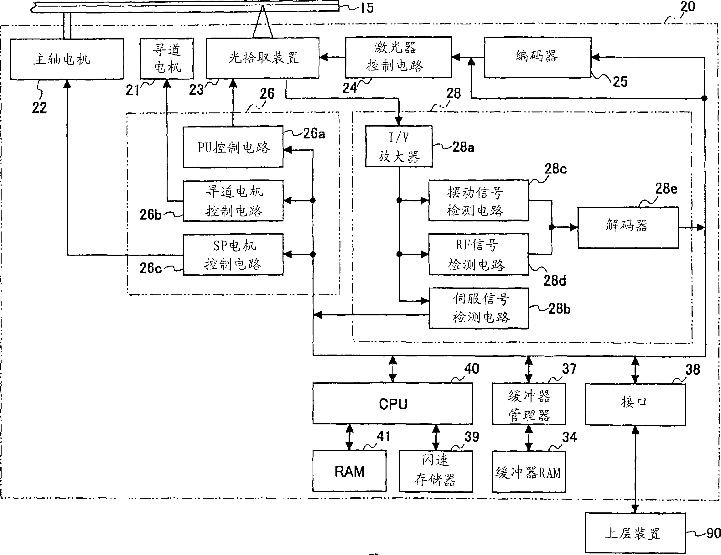
[0056] Below, based on Figure 1 to Figure 7 The first embodiment of the present invention will be described. figure 1 A schematic configuration of an optical disc device 20 as an information recording device according to the first embodiment of the present invention is shown.

[0057] Should figure 1 The illustrated optical disc device 20 includes: a spindle motor 22 for rotationally driving an optical disc 15 as an information recording medium, an optical pickup device 23, and a seek motor ( seek motor) 21, laser control circuit 24, encoder 25, servo control circuit 26, reproduced signal processing circuit 28, buffer RAM 34, buffer manager 37, interface 38, flash memory 39, CPU 40, RAM 41, etc. in addition, figure 1 The arrows shown in the circles indicate the flow of typical signals and information, and do not show all the connections between the blocks. In addition, in this first embodiment, as an example, DVD+RW is used for the optical disc 15 .

[0058] The optical ...

no. 2 approach 》

[0144] Next, use Figure 11 ~ Figure 13 A second embodiment of the present invention will be described. The second embodiment is as Figure 11 As shown, defect management is performed in both UDA1 and UDA2, which is different from the first embodiment described above. Moreover, the replacement area SA1 is arrange|positioned behind UDA1, and the some replacement area SA2 is arrange|distributed and arrange|positioned in UDA2 (here, let it be SA2-1 - SA2-4). Therefore, a part of the program stored in the flash memory 39 is different from that of the first embodiment, and the configuration of the optical disc device is the same as that of the first embodiment. Therefore, in the following description, the differences from the first embodiment will be mainly described, and the same reference numerals will be used for the same or equivalent components as those of the first embodiment, and the description will be simplified or omitted.

[0145] Logical address (LBA) such as Figur...


PUM


Abstract

An information recording device divides a data area into a plurality of partial areas (UDA1, UDA2) (step 303) and sets defect management information including a defect management method for each of the partial areas (step 305). The UDA1 is defined as an area where no defect management is performed while the UDA2 is defined as an area where defect management is performed. That is, information recorded in the UDA1 can have data continuity while information recorded in the UDA2 can have data reliability. Thus, a plurality of data having different uses and qualities can be appropriately recorded in the same information recording medium.

Description

technical field [0001] The present invention relates to a defect management information setting method, a recording method, a defect management method, a program, a recording medium, and an information recording device. A defect management information setting method of defect management information, a recording method of recording data in a data area of ​​an information recording medium, a defect management method of managing a defective area based on the defect management information, a program used in an information recording device, and a program for recording the A recording medium for a program, and an information recording device for recording data on an information recording medium. Background technique [0002] Personal microcomputers (hereinafter referred to as 'personal computers') have been widely used in text production, tabulation, and data management through databases, etc., as their performance has improved and their prices have decreased. Moreover, as an inf...

Claims


Application Information

Patent Timeline
Patent Type & Authority Applications(China)
IPC IPC(8): G11B20/12G11B20/10G11B20/18
Inventor 佐佐木启之
Owner RICOH KK
Learn More