
Pressure startup device for air compressor

An air compressor and starting device technology, which is applied to machines/engines, mechanical equipment, liquid variable capacity machinery, etc. Wide range of effects

Active Publication Date: 2007-03-07
吴全
View PDF1 Cites 0 Cited by
  • Summary
  • Abstract
  • Description
  • Claims
  • Application Information

AI Technical Summary

Problems solved by technology

Up to now, domestic and foreign enterprises still use this combination to produce air compressors (pumps) and vacuum machines (pumps), but this combination cannot solve the problem of starting the compressors (pumps) and vacuum machines (pumps) under pressure, making many designers They all searched for methods in other ways, but they were not very successful.

Method used


Image

  • Pressure startup device for air compressor
  • Pressure startup device for air compressor

Examples


Embodiment Construction

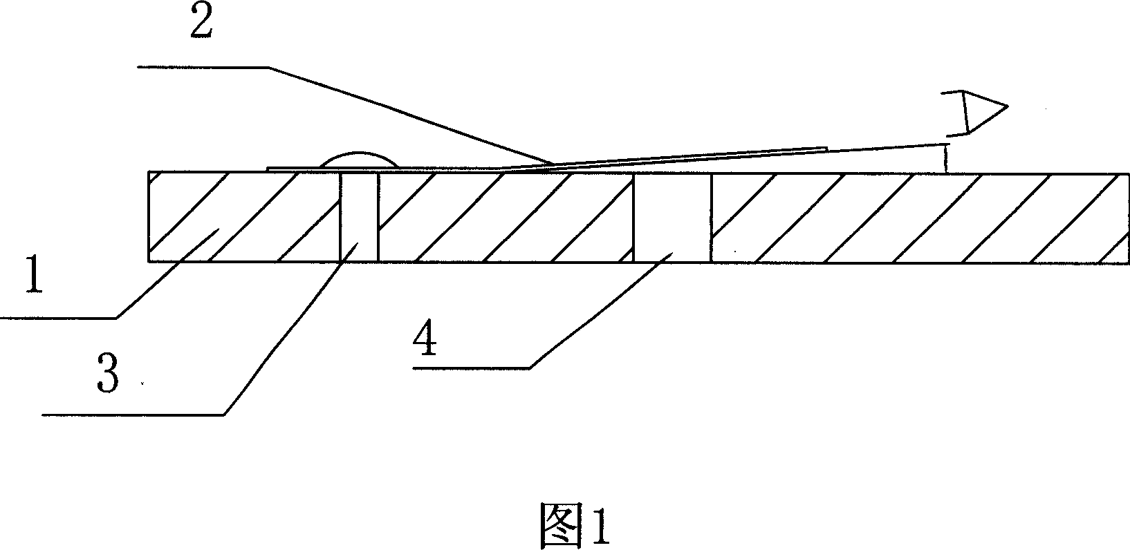
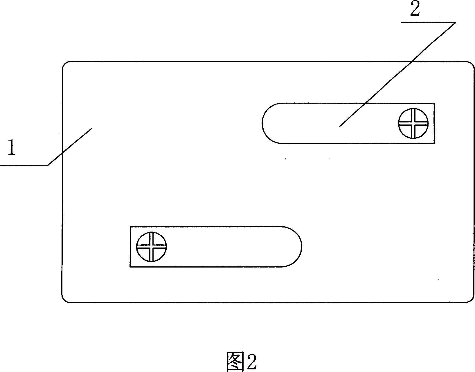
[0013] As shown in Figure 1 and Figure 2, the air compressor startup device under pressure of the present invention includes a valve plate 1 and a valve plate 2, the valve plate 1 is a metal plate, and there are inlet and outlet holes or grooves on the plate, and the valve plate 2 is formed Curved metal sheet, one end is bent up, and the other end is connected to the valve plate 1. The bending angle A is less than 25 degrees. The experiment proves that the best angle is when the angle A is 15 degrees; and it is fixed on the valve plate by screws 3 1, the valve plate 1 at the lower part of the curved part of the valve plate 2 is provided with intake and exhaust holes 4. In this embodiment, there are two valve plates fixed on the valve plate, and the directions of the fixed ends are opposite to each other, that is, when one left end When one side is fixed and the right end is bent upward, the other is fixed with the right end and the left end is bent upward. This is more conduci...


PUM


Abstract

This invention discloses one air compressor compensated start device, which is set into air compressor discharge chamber and is composed of valve board and valve slices, wherein, the valve board is opened with discharge hole or tank; it is characterized by that the valve slice is of bent shape on valve board; the valve board discharge hole or tank is set down valve slice; the said slice one end is fixed on valve board through screw nail and other end bend up for larger than 25 degrees.

Description

technical field [0001] The invention relates to an air compressor (pump) and a vacuum machine (pump) component, and more specifically relates to a pressurized starting device for an air compressor. Background technique [0002] Air compressors (pumps) and vacuum machines (pumps) at home and abroad all use the combination design of valve plate and valve plate in the structure of intake and exhaust at present, as the application number is 95225457, and the application date is November 3, 1995. Japan, the invention name is the suction and discharge valve of medium-pressure air compressor, the date of publication / announcement is June 25, 1997, and the date of authorization announcement is June 25, 1997. The suction and discharge valve of the medium-pressure air compressor The exhaust valve is composed of suction and exhaust valves. The exhaust valve plate of the exhaust valve is in the shape of a thin sheet, which is connected with a temperature rise limiter fixed on the top of ...

Claims


Application Information

Patent Timeline
Patent Type & Authority Applications(China)
IPC IPC(8): F04B49/03F04C28/06
Inventor 吴全
Owner 吴全
Learn More