Plane display adjusting method

A flat-panel display and test pattern technology, used in static indicators, cathode ray tube indicators, instruments, etc., can solve the problems of wasting personnel and equipment time and cost, flat-panel display and optical meter errors, and easy to produce errors. The effect of reducing errors, eliminating errors, and saving time and cost

Inactive Publication Date: 2007-03-07
NOVATEK MICROELECTRONICS CORP
View PDF0 Cites 3 Cited by
  • Summary
  • Abstract
  • Description
  • Claims
  • Application Information

AI Technical Summary

Problems solved by technology

[0004] Traditional calibration methods have many disadvantages
For example, each test pattern is only measured once, which is prone to errors
There is no delay before the display of the test pattern in step 102 and before the acquisition of measurement data in step 104, and the instability of the flat panel display and the

Method used


Image

  • Plane display adjusting method
  • Plane display adjusting method
  • Plane display adjusting method

Examples


Embodiment Construction

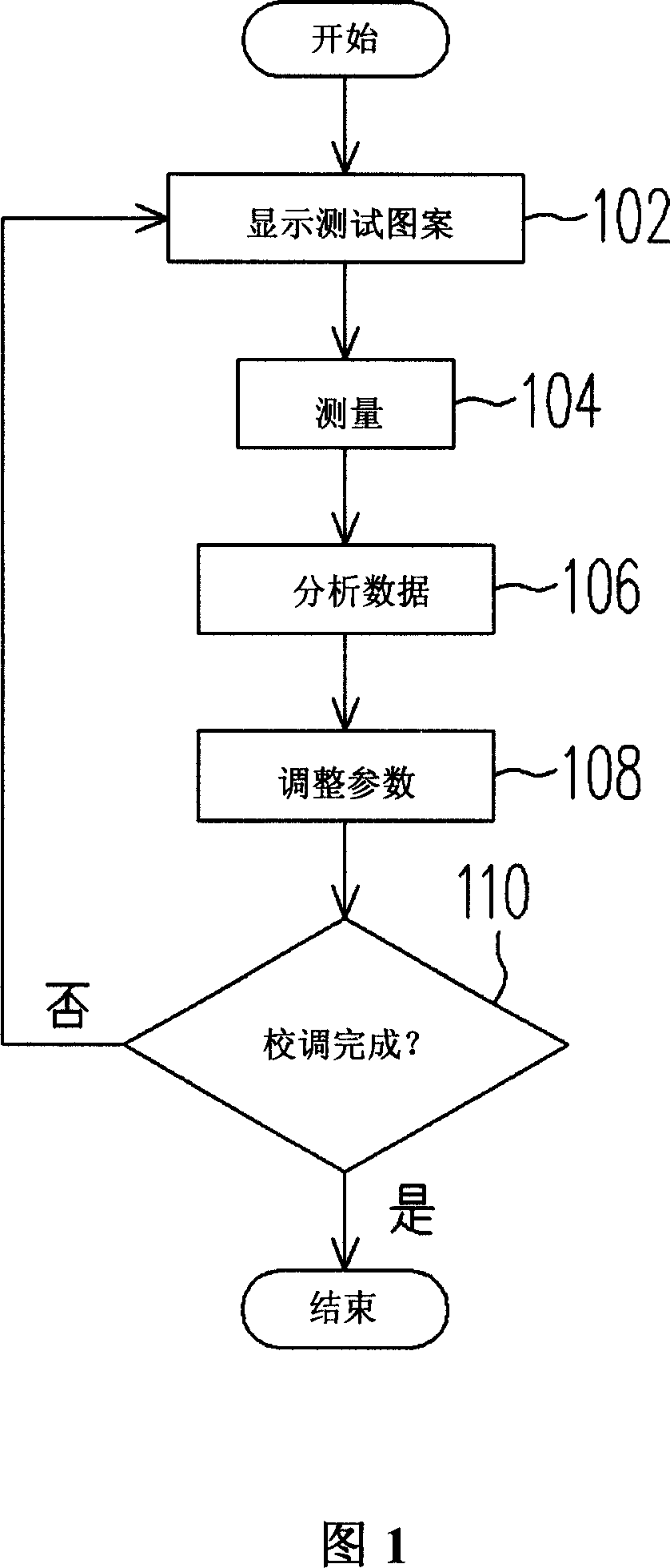
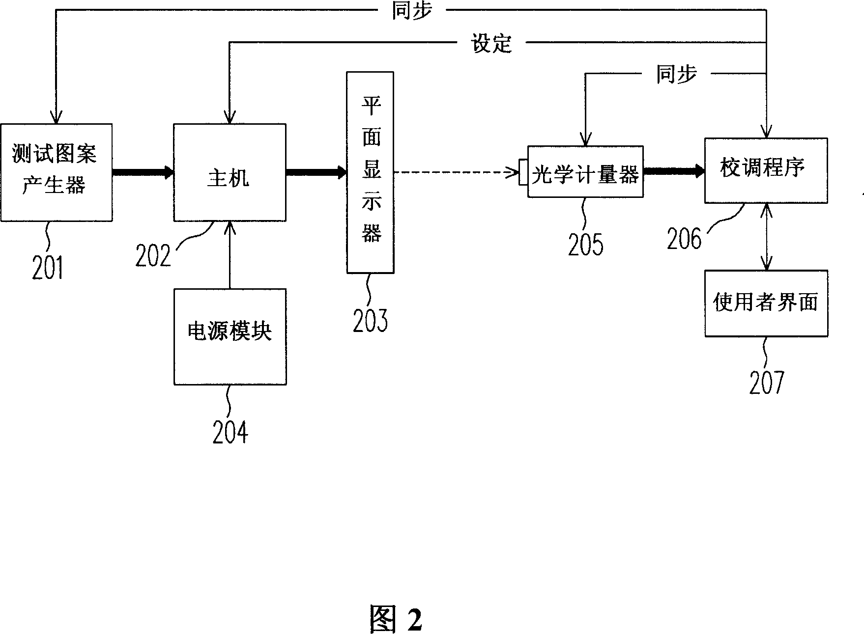
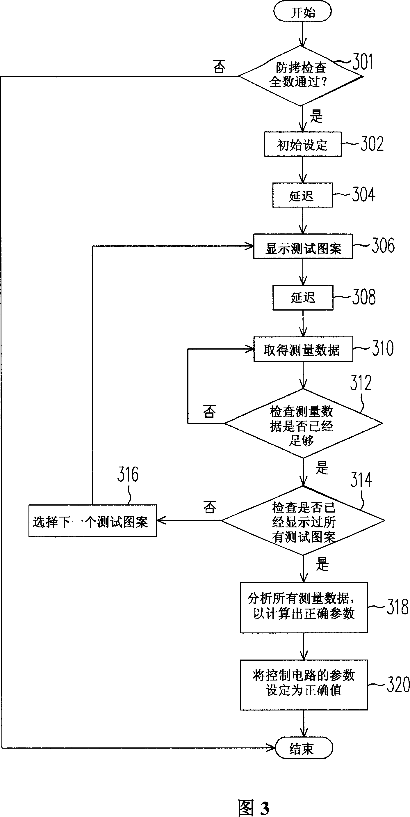
[0028] FIG. 2 is a hardware flowchart of a method for calibrating a flat panel display according to an embodiment of the invention. In this embodiment, the calibration program 206 accepts user operations through the user interface 207 to control the entire process. First, a test pattern is generated by the test pattern generator 201 and provided to the host 202 . The host 202 receives power from the power module 204 and drives the flat panel display 203 to display test patterns. Then, the optical meter 205 measures the test pattern displayed on the flat panel display 203 to obtain various data. Finally, the calibration program 206 collects and analyzes the above-mentioned measurement data, and then sets the relevant parameters of the control circuit of the flat panel display 203 to correct values.

[0029] Generally, there are many display characteristics that need to be calibrated for flat panel displays, such as brightness, color, and stripe display. For different display...


PUM


Abstract

The present invention relates to a plane display adjusting method comprising the following steps: initial setting the plane display and optical meter; delaying a preset time; displaying a test pattern on the plane display; delaying another preset time; repeatedly measuring the test pattern to obtain sufficient value by the optical measure till the enough data are obtained; repeatedly displaying the test pattern to show all the ones; finally, analyzing all the measuring value to calculate the correct parameters of the control circuit, and setting the parameters of the control circuit.

Description

technical field [0001] The invention relates to a method for calibrating a flat-panel display, and in particular to a method for calibrating a flat-panel display for setting parameters of a control circuit. Background technique [0002] A flat panel display, such as a thin filmtransistor liquid crystal display (TFT LCD for short), is composed of many optical, chemical and circuit components, among which there are many variables that affect display characteristics such as brightness and color. . Examples of variables in the controller include decoders, de-interlace, and noise filtering. Variations in LCD modules include backlights, thin film transistors, and color filters. If the performance of individual parts is not strictly controlled during mass production, the display quality of the final product will inevitably vary greatly. In order to control the difference in image quality of the final product within an acceptable range, the manufacturer must perform calibration. ...

Claims


Application Information

Patent Timeline
IPC IPC(8): G09G3/36G09G3/20G09G5/00G02F1/133
Inventor 沈毓铨黄伟哲
Owner NOVATEK MICROELECTRONICS CORP
Why Eureka
Try Eureka