Rapid movement estimating method

A fast motion and motion estimation technology, applied in TV, standard conversion, electrical components, etc., can solve the problems of slowing motion estimation convergence speed and decreasing smoothness of motion vector field, and achieve the effect of accelerating convergence speed and improving smoothness

Inactive Publication Date: 2007-03-07
深圳清研创业投资有限公司
View PDF2 Cites 87 Cited by
  • Summary
  • Abstract
  • Description
  • Claims
  • Application Information

AI Technical Summary

Problems solved by technology

[0007] In order to overcome the deficiencies of the above-mentioned prior art, a fast motion estimation method is provided, thereby solving the problems th

Method used


Image

  • Rapid movement estimating method
  • Rapid movement estimating method
  • Rapid movement estimating method

Examples


Embodiment Construction

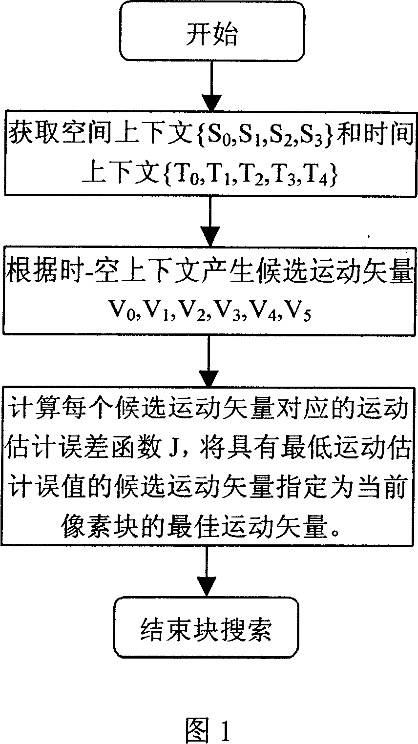
[0031] Please refer to FIG. 1, the fast motion estimation method of the present invention includes the following steps:

[0032] First, divide each frame of video image into non-overlapping image blocks; secondly, determine the spatial context {S for each current pixel block 0 , S 1 , S 2 , S 3} and temporal context {T 0 , T 1 , T 2 , T 3 , T 4}; Generate six candidate motion vectors (V 0 , V 1 , V 2 , V 3 , V 4 , V 5); calculate the motion estimation matching error function J corresponding to each candidate motion vector, and designate the candidate motion vector with the lowest matching error value as the best motion vector of the current pixel block.

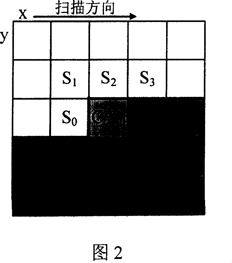
[0033] Please also refer to Figure 2, the method of determining the spatial context and temporal context for each current sub-block in the above steps is as follows:

[0034] First, in the current frame, select the motion vector S of the right and left sub-block of the current block (C) 0 , the motion vector S ...


PUM


Abstract

This invention relates to one rapid movement estimation method, which comprises the following steps: a, dividing each frame of images into several blocks and determining vector space upper and down message on each current image composed of upper and down messages to determine several prepare motion vector; computing each prepare motion vector matching error values with low motion matching error values with current pixel module designed as motion vector step.

Description

technical field [0001] The present invention relates to a fast motion estimation method, in particular to a high-performance method for improving the smoothness of estimated vector fields in digital video signal processing (such as field / frame rate converters, deinterlacing converters) or digital video coding. Fast motion estimation method. Background technique [0002] As we all know, the current applications of motion estimation in the field of digital video can be roughly divided into two categories: one is video compression coding, and the other is video post-processing, such as field / frame rate converters, deinterlacing converters, and so on. [0003] Existing video compression coding standards (such as H.26x and MPEG-2) adopt a hybrid structure coding framework based on block motion compensation + residual DCT transform, which requires block motion estimation as support. The motion estimation and motion compensation in the video compression coding standard is a nonlin...

Claims


Application Information

Patent Timeline
IPC IPC(8): H04N7/26H04N7/01H04N19/51
Inventor 张宗平刘鲲彭吉虎田华
Owner 深圳清研创业投资有限公司
Why Eureka
Try Eureka