Supercharge Your Innovation With Domain-Expert AI Agents!

Chucking device

A technology of clamping device and main body, which is applied in the field of disk devices, and can solve problems such as large loads

Inactive Publication Date: 2007-03-07
PANASONIC CORP
View PDF1 Cites 4 Cited by
  • Summary
  • Abstract
  • Description
  • Claims
  • Application Information

AI Technical Summary

Problems solved by technology

Therefore, when the disk is inserted, the sliding action of the claw body into the hub body requires a large load

Method used


Image

  • Chucking device
  • Chucking device
  • Chucking device

Examples


Embodiment Construction

[0087] Next, a clamping device according to an embodiment of the present invention will be described.

[0088] First, the hub main body constituting the clamp device according to the present embodiment will be described.

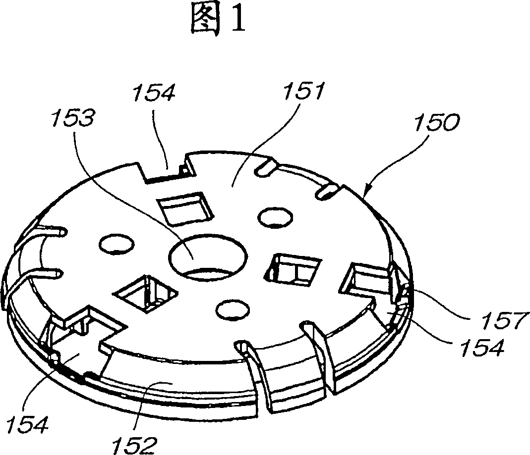
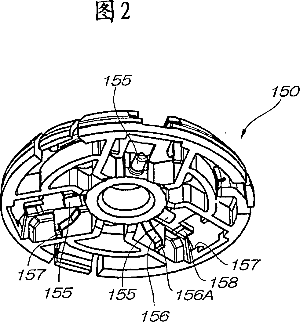
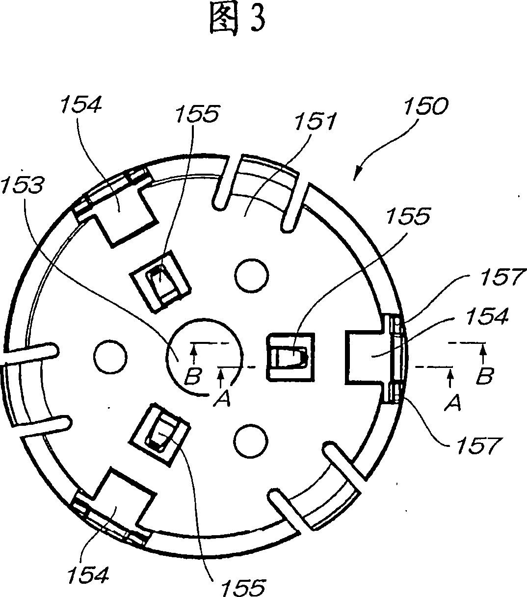
[0089] 1 is an upper side perspective view of a hub body of a clamping device according to the present embodiment, FIG. 2 is a lower side perspective view of the hub body, FIG. 3 is a front view of the hub body, and FIG. 4 is a rear view of the hub body. 5 is a side view of the hub main body, FIG. 6 is a sectional view of A-A in FIG. 3 , and FIG. 7 is a sectional view of B-B in FIG. 3 .

[0090] The hub body 150 of the turntable is formed into a dish shape by a disc-shaped upper surface 151 and side surfaces 152 erected on the outer periphery of the upper surface 151 . In the center portion of the upper surface 151, a motor shaft hole 153 is formed to engage with the rotation shaft of the spindle motor.

[0091] Three pawl openings 154 are radially provide...


PUM


Abstract

A chucking device holding a disk by pressing a disk center hole part by a plurality of claw bodies movably installed on a turntable in the radial direction of a hub body. The chucking device comprises elastic members energizing the claw bodies to the outer side of the hub body. The claw bodies further comprise claw parts in contact with the disk and claw side stoppers restricting the movement thereof to the outer side by the elastic members. The hub body further comprises a claw opening part allowing a claw part to be projected to the outside and a hub side stopper in contact with the claw side stopper. The chucking device is characterized in that a downward guide face is formed on the lower side of the tip part of the claw part, an upward receiving face is formed on the hub body at a position opposed to the downward guide face, the downward guide face is formed of at least a first tilted face and a second tilted face, the first tilted face is brought into the upward receiving face when the claw part is pressed by the disk from the upper side at a time when or before the tip part of the claw part is inserted into the center hole part of the disk, the second tilted face is brought into contact with the upward receiving face after the tip part of the claw part is inserted into the center hole part of the disk, and the second tilted face is reduced in an angle relative to the pressing direction less than the first tilted face.

Description

technical field [0001] The present invention relates to a disc device for recording or reproducing on a disc-shaped recording medium such as a CD or a DVD, and particularly relates to a clamping device suitable for a so-called slot-in type disc device in which a disc can be directly inserted or ejected directly from the outside. . Background technique [0002] Conventional disk devices often employ a loading method in which a disk is placed on a tray or turntable, and the tray or turntable is mounted in the device main body. [0003] However, in this loading method, since a tray or a turntable is required, there is a limit in reducing the thickness of the disk drive main body. [0004] On the other hand, as a suction-type disk device, it has been proposed to pull in a disk by bringing a transport roller into contact with the surface of the disk (for example, Patent Document 1). [0005] (Patent Document 1) [0006] Japanese Patent Application Publication No. 7-220353 [...

Claims


Application Information

Patent Timeline
Patent Type & Authority Applications(China)
IPC IPC(8): G11B17/028
Inventor 太田秀彦
Owner PANASONIC CORP
Features
  • R&D
  • Intellectual Property
  • Life Sciences
  • Materials
  • Tech Scout
  • Unparalleled Data Quality
  • Higher Quality Content
  • 60% Fewer Hallucinations
Learn More