Brake device for elevator

A braking device and elevator technology, which is applied to elevators, transportation and packaging, elevators, etc. in buildings, can solve problems such as increasing the current flowing into the coil, and achieve the effect of reducing braking

Inactive Publication Date: 2007-03-14
MITSUBISHI ELECTRIC CORP
View PDF1 Cites 10 Cited by
  • Summary
  • Abstract
  • Description
  • Claims
  • Application Information

AI Technical Summary

Problems solved by technology

[0004] In the braking device of the above-mentioned existing elevator, when switching from the braking state to the releasing state, since it is necessary to compress the spring with a force greater than the force corresponding to the braking force, a large amount of energy is required, and the inflow must be increased. coil current

Method used


Image

  • Brake device for elevator
  • Brake device for elevator
  • Brake device for elevator

Examples


no. 1 approach

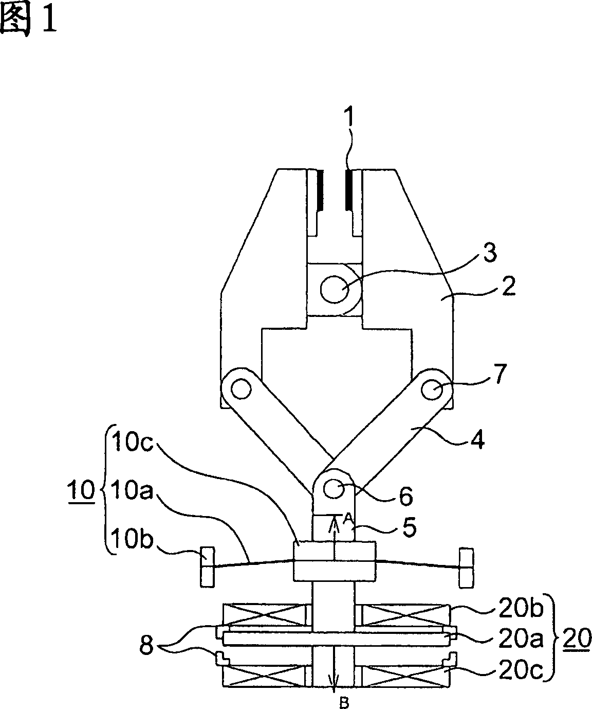
[0024] Fig. 1 is a block diagram showing an elevator braking device according to a first embodiment of the present invention. The outer edge portion of the disc spring 10a is supported by the fixing portion by the support portion 10b. And the inner edge portion (central portion) of the disc spring is fixed to the movable plunger 5 by the support portion 10c. One end of the movable inserting rod 5 is connected with one end of the connecting rod 4 through the supporting shaft 6 , and the connecting rod 4 can rotate relative to the supporting shaft 6 . The other end of the link 4 is connected to the end of the arm 2 through a support shaft 7 so that it can freely rotate relative to the support shaft 7 . The arm 2 is rotatably fixed on a fixed shaft 3 . Attached to the front end of the arm 2 is a slide member 1 that is in direct contact with a disk member, a guide rail (not shown), or the like. At the other end of the movable plunger 5, a drive unit 20 for the movable plunger i...

no. 2 approach

[0031] Fig. 5 is a block diagram showing a braking device for an elevator according to a second embodiment of the present invention. The magnet spring 40 is composed of a permanent magnet 40a, a movable iron core 40b integrally fixed to the movable plunger 5 and operated, and a yoke 40c provided to surround these components. Other structures are the same as those of the first embodiment. In addition, 1 to 4, 6, and 7 constitute a brake mechanism, 40 constitutes a first drive mechanism, and 20 constitutes a second drive mechanism.

[0032] The operation will be described below. FIG. 5 shows a state in which a disc member or a guide rail is gripped between slide members 1 and a braking force is exerted. At this time, the movable iron core 40b is pressed in the arrow A direction by the magnetic flux in the arrow C direction of the permanent magnet 40a. Like this, movable inserting rod 5 is also stressed in the direction of arrow A, and the supporting shaft 7 of connecting rod ...

no. 3 approach

[0037] Fig. 8 is a configuration diagram showing an elevator braking device according to a third embodiment of the present invention. The electromagnetic attraction device 50 is fixed on the movable plunger 5 by a permanent magnet 50a and forms a movable iron core 50b that moves integrally, and the braking coils are respectively arranged on the opposite sides (mutually opposite) of the permanent magnet 50a both sides. 51a, a release coil 51b, and a yoke 50c provided to surround the coils 51a, 51b, the permanent magnet 50a, and the movable iron core 50b. Other structures are the same as those of the first embodiment. In addition, 1 to 4, 6, and 7 constitute a brake device, 50 constitutes a first drive mechanism, and 51a, 51b constitute a second drive mechanism.

[0038] The operation will be described below. FIG. 8 shows a state in which a disc member or a guide rail is gripped between the slide members 1 and a braking force is exerted. At this time, neither the brake coil 5...


PUM


Abstract

The invention provides a brake device for an elevator that can reduce the energy required for braking and release, which has: a movable plunger (5), brake mechanisms (1-4), (6), (7), A drive mechanism (10) and a second drive mechanism (20), the brake devices (1-4), (6), (7) are connected to one end of the movable plunger, and The movement in the direction is switched to the braking state and the releasing state; the first driving mechanism (10) uses mechanical or magnetic power to make the movable plunger move in the movable range of the axial direction switching to the braking state and the releasing state. Reverse in the middle to keep it pressed on the brake side or the release side; the second drive mechanism uses electromagnetic force, in order to switch between the brake state and the release state, resist the pressing force of the above-mentioned first drive mechanism and push the above-mentioned movable insert The lever is driven from the braking side or the releasing side to a reverse position in the middle of the above-mentioned movable range.

Description

technical field [0001] The present invention relates to braking devices for elevators. Background technique [0002] The braking state of the existing elevator braking device is maintained by the pressing force formed by the spring, and the released state is maintained by the magnetic force of the permanent magnet. To switch from the brake state to the release state, direct current is applied to the electromagnet coil to generate a strong magnetic field in the same direction as the permanent magnet, thereby resisting the force of the spring and attracting the armature (Amachua). Even if the direct current is cut off after the suction is completed, the magnetic force of the permanent magnet can keep the armature in the suction state. Switching from the release state to the brake state is conducted by passing direct current to the coil to generate a magnetic force that cancels the magnetic force of the permanent magnet (for example, refer to Patent Document 1). [0003] Pate...

Claims


Application Information

Patent Timeline
Patent Type & Authority Applications(China)
IPC IPC(8): B66B5/18B66B11/08
CPCB66B5/18
Inventor 木川弘上田隆美冈本健一
Owner MITSUBISHI ELECTRIC CORP
Why Eureka
Try Eureka