Guide bar arrangement of warp knitting machine

A warp knitting machine and bar technology, which is applied in the field of bar devices, can solve the problems of increasing the width and speed of the driving power machine, increasing the mass, and accelerating, and achieves the effect of reducing the risk of wear and tear.

Active Publication Date: 2014-07-16
KARL MAYER STOLL R&D GMBH
View PDF9 Cites 1 Cited by
  • Summary
  • Abstract
  • Description
  • Claims
  • Application Information

AI Technical Summary

Problems solved by technology

This also leads to an increase in mass, which has an adverse effect on the working speed of the machine, since the mass of the bar must be accelerated and braked during any working stroke of the machine
Drive power thus rises excessively with respect to machine width and speed
In addition, there will be a lot of wear and tear

Method used


Image

  • Guide bar arrangement of warp knitting machine
  • Guide bar arrangement of warp knitting machine
  • Guide bar arrangement of warp knitting machine

Examples


Embodiment Construction

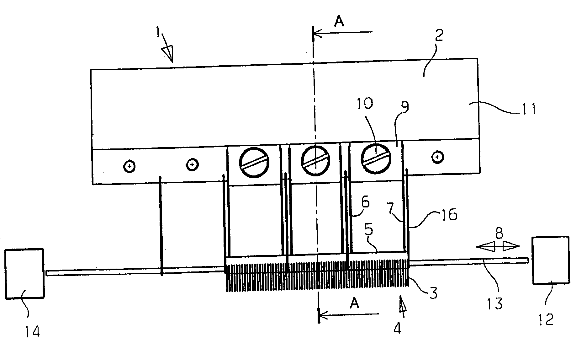
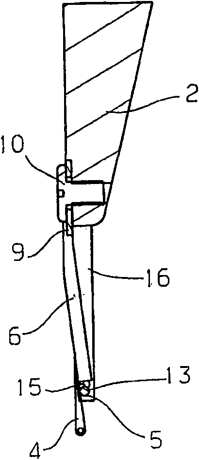
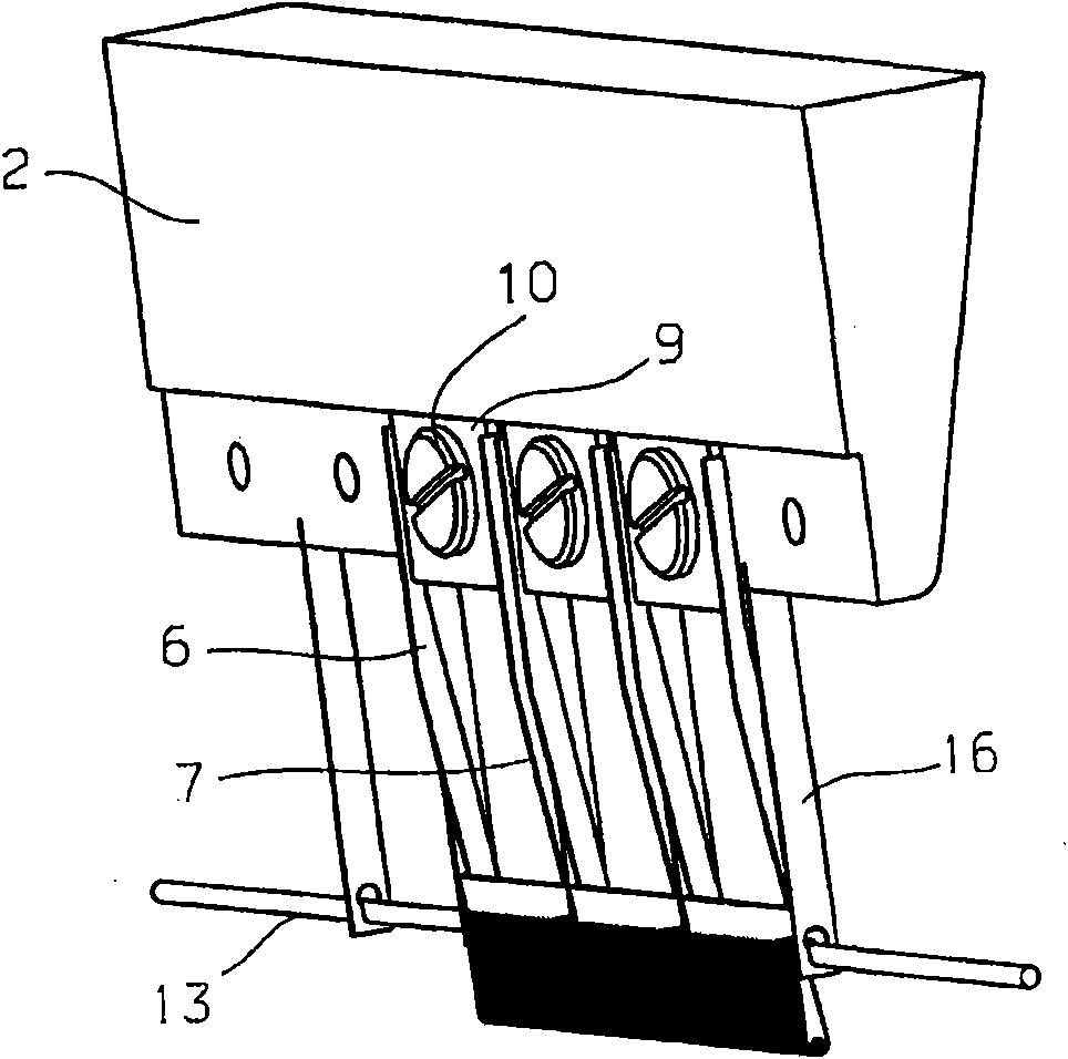
[0033] figure 1 It is a schematic diagram of a bar device 1 , which has a bar 2 and a plurality of guide needles 3 . A plurality of guide needles 3 form fan-shaped plates 4 respectively. Each sector plate 4 has a bracket 5 . The distance of the brackets 5 along the direction of successive arrangement of the guide needles 3 is, for example, 2 inches. It then has, for example, 48 guide needles 3 .

[0034] The bracket 5 is fixed on the comb bar 2 through two connection mechanisms 6,7. The connecting means 6 , 7 allow the carriage 5 and thus the sector plate 4 with the guide needles 3 arranged therein to be moved relative to the bar 2 in the traverse direction 8 , ie in the direction of the successive arrangement of the guide needles 3 . The connecting means 6 , 7 are arranged on a fastening part 9 which is fastened to the bar 2 by means of screws 10 . A threaded hole 11 is provided on the bar 2 for each fastening element 9 .

[0035] A drive mechanism 12 is provided in ord...


PUM


Abstract

The arrangement (1) has multiple guide needles (3) combined into needle segments (4) in a group-wise manner. The needle segments are connected with a bar (2) over springs and joint levers transverse to a displacement direction (8), where the bar is movable in the displacement direction. The springs are designed as plate springs. A drive (12) is engaged at the needle segments for moving the guide needles in the displacement direction. Connection units (6, 7) i.e. plate springs, are engaged at a carrier (5) between the bar and the needle segments, which are tightened at a drive element (13).

Description

technical field [0001] The present invention relates to a bar device of a warp knitting machine, which has a bar, a plurality of guide needles forming a fan-shaped plate in groups, and a drive mechanism for causing the guide needles to produce traverse motion. Background technique [0002] Such a bar arrangement is known, for example, from DE 44 35 562 C2. [0003] Another bar arrangement of this type is known from DE 1 857 100 U1. Here, the bar is suspended on the bar by means of ball guides, so that the bar can be moved back and forth in the traverse direction by the drive. [0004] In order to produce knitwear by means of a warp knitting machine, the yarn must be wound around the knitting needles by means of guide needles, sometimes called eyelet needles, during the knitting. For this reason, guide needle is usually fixed on the bar, and bar is moved back and forth on the traversing direction by drive mechanism. During the back and forth movement along the traversing d...

Claims


Application Information

Patent Timeline
Patent Type & Authority Patents(China)
IPC IPC(8): D04B27/24
CPCD04B27/26
Inventor K·米斯塔J·菲舍尔
Owner KARL MAYER STOLL R&D GMBH
Why Eureka
Try Eureka