Combined die cutting tool

A combined type and cutting tool technology, which is applied in metal processing and other directions, can solve problems such as insufficient contact of fittings or bottom rollers, failure to meet the installation requirements of cutter rollers, and inability to adjust the position of transmission gears, so as to reduce the risk of equipment wear and improve reliability. Operability and the effect of improving the efficiency of installation and control

Pending Publication Date: 2020-05-08
中融飞腾(北京)科技有限公司
View PDF10 Cites 1 Cited by
  • Summary
  • Abstract
  • Description
  • Claims
  • Application Information

AI Technical Summary

Problems solved by technology

However, in view of the structural limitations of the current die-cutting tool, the adjustment of its size is cumbersome
[0004] The existing die-cutting tool is composed of a knife roller and a transmission gear fixed on the shaft head of the knife roller by screws. When adjusting the size of the knife roller, the knife roller needs to be disassembled from the equipment, and the operation is very cumbersome; the knife adjuster solves the problem of The problem of inconvenient adjustment of the cutter roller, but the existing cutter roller is not compatible with various types of cutter adjusters, matching them one by one will undoubtedly increase the cost of the enterprise; in addition, the position of the transmission gear on the cutter roller cannot be adjusted, which cannot meet the needs of different lengths of cutters. The installation requirements of the rollers on the same type of die-cutting machine; and, due to the influence of the position between the pillows, there is a risk of damaging the driving gear on the die-cutting machine during work, which will directly cause serious wear or even damage to the equipment. At the same time, due to the influence of the position between the pillows, It is impossible to install the knife adjuster to the inner side of the transmission gear, and there is a problem of insufficient contact with the matching surface of the accessories or the bottom roller, and there is a risk of vulnerability
[0005] Through searching, no published patent documents identical or similar to the patent of the present invention have been found

Method used


Image

  • Combined die cutting tool
  • Combined die cutting tool
  • Combined die cutting tool

Examples


Embodiment 1

[0042] This embodiment 1 belongs to the above-mentioned situation one.

[0043] Install:

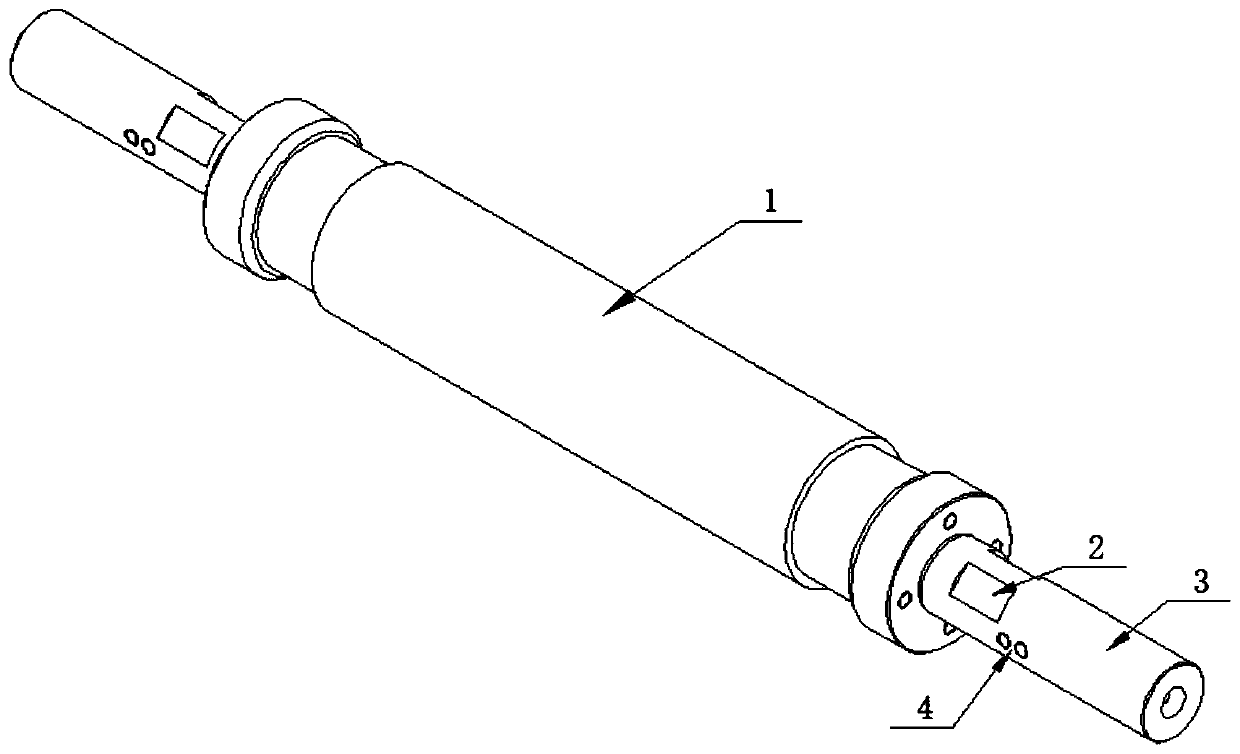
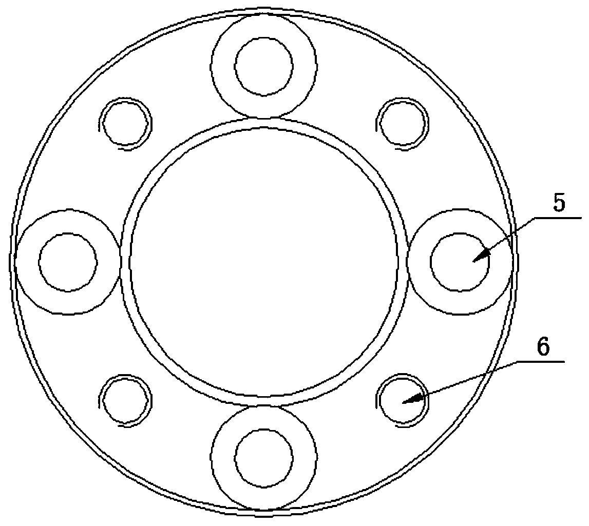
[0044] 1. Install the knife adjuster on the cutter body, use the screw to pass through the countersunk hole on the knife adjuster, and fix it on the cutter body;

[0045] 2. Install the pin on the cutter gear in advance, then install the cutter gear on the cutter body, align the pin with the pin adjustment hole on the cutter adjuster, and then overlap the cutter gear with the cutter adjuster, and adjust the two holes through the pin adjustment hole. The screw on the side limits the pin and locks it to the middle position for adjustment;

[0046]3. Install the spring and retaining ring on the shaft head so that the end face of the retaining ring meets the tool gear to prevent slipping.

[0047] adjust:

[0048] After installing the tool to the equipment station as required, when the size needs to be adjusted, the size adjustment function can be realized by adjusting the screws in the l...

Embodiment 2

[0050] Embodiment 2 belongs to above-mentioned situation two

[0051] Install:

[0052] 1. First, install the interdental pad on the cutter body through screws;

[0053] 2. Install the pin on the cutter gear in advance, then install the cutter gear on the cutter body, with the pin facing the outside, and use the other side of the cutter gear to coincide with the interdental pad;

[0054] 3. Install the knife adjuster to the cutter body. When installing, pay attention to align the pin adjustment hole on the knife adjuster with the pin. After the knife adjuster coincides with the cutter gear, the pin is limited by the screws on both sides of the pin adjustment hole. , and lock it to the middle position for adjustment;

[0055] 4. Turn the knife adjuster so that the two locking screw holes on the top are aligned with the locking platform on the shaft head, and fix the knife adjuster at the shaft head by passing two screws through the locking screw holes.

[0056] adjust:

[0...

Embodiment 3

[0059] Embodiment 3 belongs to above-mentioned situation two

[0060] Install:

[0061] 1. First, install the interdental pad on the cutter body through screws;

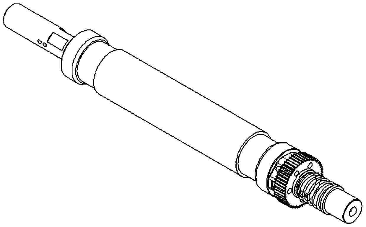
[0062] 2. It is necessary to install and fasten the cutter gear, gasket and high-precision cutter adjuster with screws in advance;

[0063] 3. Install the installed cutter gear, gasket and high-precision cutter adjuster to the cutter body at the shaft head according to the direction shown in the drawing, so that the cutter gear and the interdental pad are overlapped;

[0064] 4. Use screws to install to the threaded holes of the cutter body through the mounting holes set on the outer edge of the high-precision cutter adjuster to fix it.

[0065] adjust:

[0066] After installing the tool to the equipment station as required, when the size needs to be adjusted, the size adjustment function can be realized by adjusting the size adjustment function of the high-precision knife adjuster.

[0067] The high-precision kn...


PUM


Abstract

The invention relates to a combined die cutting tool. The combined die cutting tool is characterized by comprising a tool body, a tool gear and a tool adjuster; the tool gear and the tool adjuster aremounted on a shaft head of the tool body; a circle of locking platform is arranged on a head body of the shaft head of the tool body in a spaced mode; the position, at the front end of the locking platform, of the head body is provided with threaded holes. The combined die cutting tool provided by the invention is scientific and reasonable in structural design and has the advantages of being convenient to operate, high in compatibility, capable of reducing the die cutting cost, meeting the requirements for die cutting and reducing the equipment wear risk and easy to realize.

Description

technical field [0001] The invention belongs to the field of supporting devices for die-cutting machines, and relates to a die-cutting tool, in particular to a combined die-cutting tool. Background technique [0002] The die-cutting tool is an important part of the rotary die-cutting machine. Generally, according to the needs of the die-cutting products, multiple groups are set on the die-cutting machine to realize continuous multi-channel die-cutting processing. When working, bottom rollers are installed under each set of die-cutting knives, and the two are synchronously rotated in opposite directions through gear transmission, so as to complete the die-cutting of raw materials. [0003] In order to ensure the precision of die-cut products, it is necessary to adjust the relative position of each tool during die-cutting, so as to realize the precise matching with the die-cutting position in the previous die-cutting process. However, in view of the structural limitations of ...

Claims


Application Information

Patent Timeline
Patent Type & Authority Applications(China)
IPC IPC(8): B26F1/44B26D7/26
CPCB26F1/44B26D7/2614B26D7/2628
Inventor 肖建阳蔡玉星苏强胡延峰周立国董红雨张立红
Owner 中融飞腾(北京)科技有限公司
Why Eureka
Try Eureka