
Control method for a continuously variable transmission

A technology of continuously variable transmission and control method, applied in the direction of transmission control, elements with teeth, belt/chain/gear, etc., can solve the problems of increasing high level, instability, transmission damage, etc., and achieve cost saving Effect

Active Publication Date: 2007-03-14
ROBERT BOSCH GMBH
View PDF4 Cites 4 Cited by
  • Summary
  • Abstract
  • Description
  • Claims
  • Application Information

AI Technical Summary

Problems solved by technology

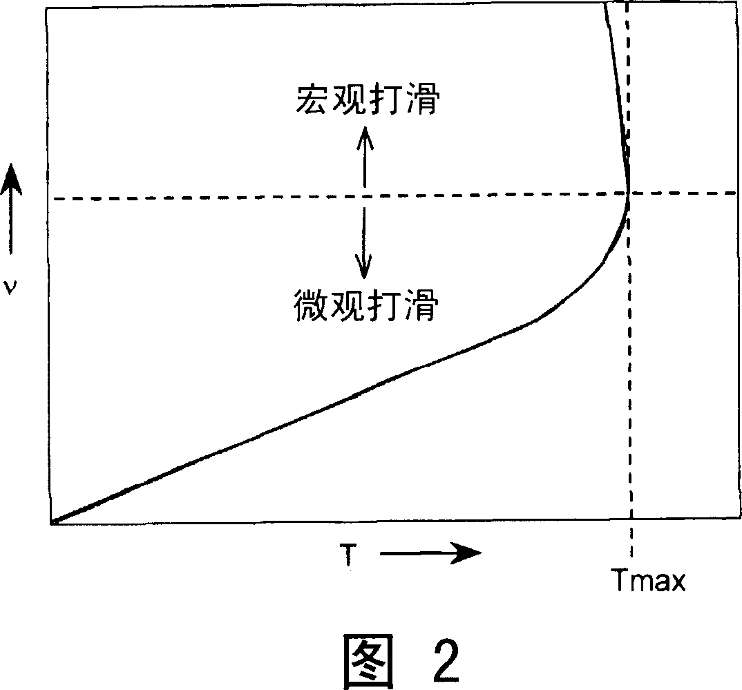
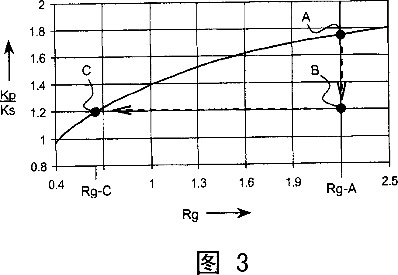
[0008] Thus, the problem arises that, where the ideal slip ratio is set close to the optimal transmission efficiency, the actual slip ratio during operation may be at least temporarily within the macro-slip range, e.g. due to unexpected and / or sudden increases in torque levels In addition, for example, when the transmission ratio of the transmission is changed, that is, when changing gears, a change in the force ratio between the individual clamping forces is always involved, for example by reducing one of the two clamping forces
As previously pointed out, slip is unstable in the macro-slip range and can easily increase to high levels to cause permanent damage to the transmission

Method used


Image

  • Control method for a continuously variable transmission
  • Control method for a continuously variable transmission
  • Control method for a continuously variable transmission

Examples


Embodiment Construction

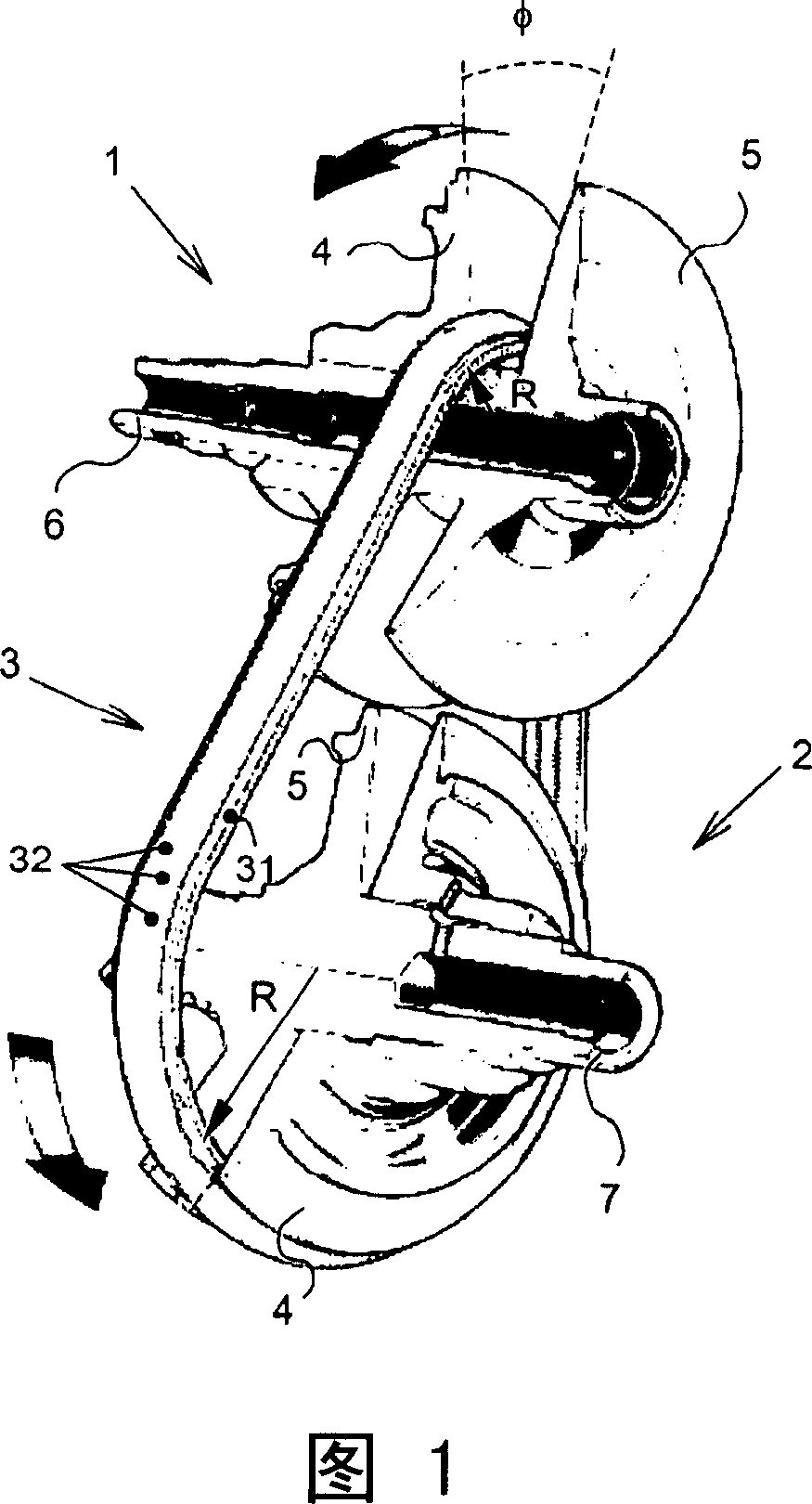
[0026]FIG. 1 shows a main part showing a continuously variable transmission used in a vehicle such as a passenger car. The variator is known per se and comprises a primary pulley 1 and a secondary pulley 2 with a drive belt 3 arranged between them, each pulley comprising two pulley pulleys 4 , 5 respectively. The pulley sheaves 4, 5 are of conical form to define wedge-shaped grooves, and at least one sheave 4 of each pulley 1, 2 is axially movable along a respective shaft 6, 7, the sheaves 4, 5 placed on the axis. In addition, the transmission comprises actuating means (not shown in the figures), usually electrically controllable and hydraulically actuated, capable of applying an axial force Fax to said one disc 4 in such a way that The drive belt 3 can be clamped between the respective pulleys 4, 5 and can move between the pulleys 1, 2 by means of friction in the conical (wedge-shaped) contact surface between the pulleys 4, 5 and the drive belt 3 transmission of mechanical ...


PUM


Abstract

A control method for controlling a continuously variable transmission having two pulleys (1, 2) each provided with two pulley sheaves (4, 5), which together define a tapering groove within which a drive belt (3) is clamped at a radial position, i.e. running radius (R), with the aid of a substantially axially oriented clamping force, a change in a force ratio between the clamping force at the location of the primary pulley (1) and at the location of the secondary pulley (2) for the purpose of a desired change in a transmission ratio of the transmission, which is determined by the quotient of the running radius (R) of the drive belt (3) at the location of the primary pulley (1) and at the location of the second pulley (2), being realized, at least initially, by a suitably adapted increase in a respective clamping force.

Description

technical field [0001] The present invention relates to a control method when mechanical power is transmitted between the primary pulley and the secondary pulley through a circulating transmission element arranged between the primary pulley and the secondary pulley of a belt-pulley type continuously variable transmission. The method is used to control the clamping force of the primary pulley and the clamping force of the secondary pulley in a continuously variable transmission, wherein the continuously variable transmission is particularly suitable for motor vehicles, and the circulating transmission element can be referred to as a transmission belt for short; the control method Described in the preamble of claim 1. The invention also relates to a continuously variable transmission designed to operate according to the aforementioned control method. Background technique [0002] Control methods and transmissions of this type are known, for example from European patent public...

Claims


Application Information

Patent Timeline
IPC IPC(8): F16H61/00F16H61/662
CPCF16H61/66272
Inventor 布拉姆·邦森
Owner ROBERT BOSCH GMBH
Learn More