Rolling bearings and aero engines

A technology of rolling bearings and bearings, which is applied in the direction of shafts and bearings, bearing components, mechanical equipment, etc., can solve the problems of temporary fixes, not permanent fixes, bearing slippage, complex structure, etc., and achieve the effects of reducing slipping rate, preventing slipping, and reducing weight

Active Publication Date: 2019-05-07
AECC SHANGHAI COMML AIRCRAFT ENGINE MFG CO LTD +1
View PDF5 Cites 0 Cited by
  • Summary
  • Abstract
  • Description
  • Claims
  • Application Information

AI Technical Summary

Problems solved by technology

[0007] Existing rolling bearings generally require a cage to position the rolling elements, and the structure is complex
Moreover, the above measures can only prevent and control the slippage of the aero-engine roller bearings to a certain extent, the degree of slippage has been alleviated, and the failure rate has been slightly reduced, but the problem of bearing slippage still exists, and it is not a permanent cure.

Method used


Image

  • Rolling bearings and aero engines
  • Rolling bearings and aero engines
  • Rolling bearings and aero engines

Examples


Embodiment Construction

[0026] The technical solutions of the present invention will be described in further detail below with reference to the accompanying drawings and embodiments.

[0027] The specific embodiments of the present invention are for the convenience of further description of the concept of the present invention, the technical problems to be solved, the technical features constituting the technical solution and the technical effects brought about. It should be noted that the description of these embodiments does not constitute a limitation of the present invention. In addition, the technical features involved in the embodiments of the present invention described below may be combined with each other as long as they do not conflict with each other.

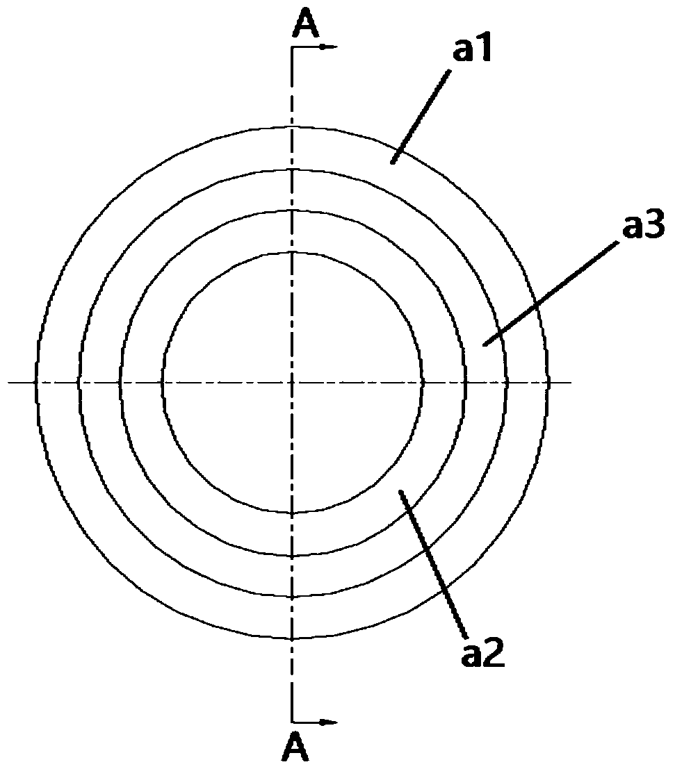
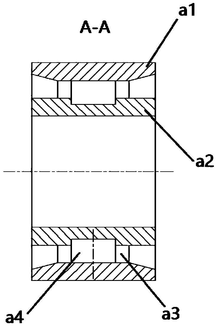
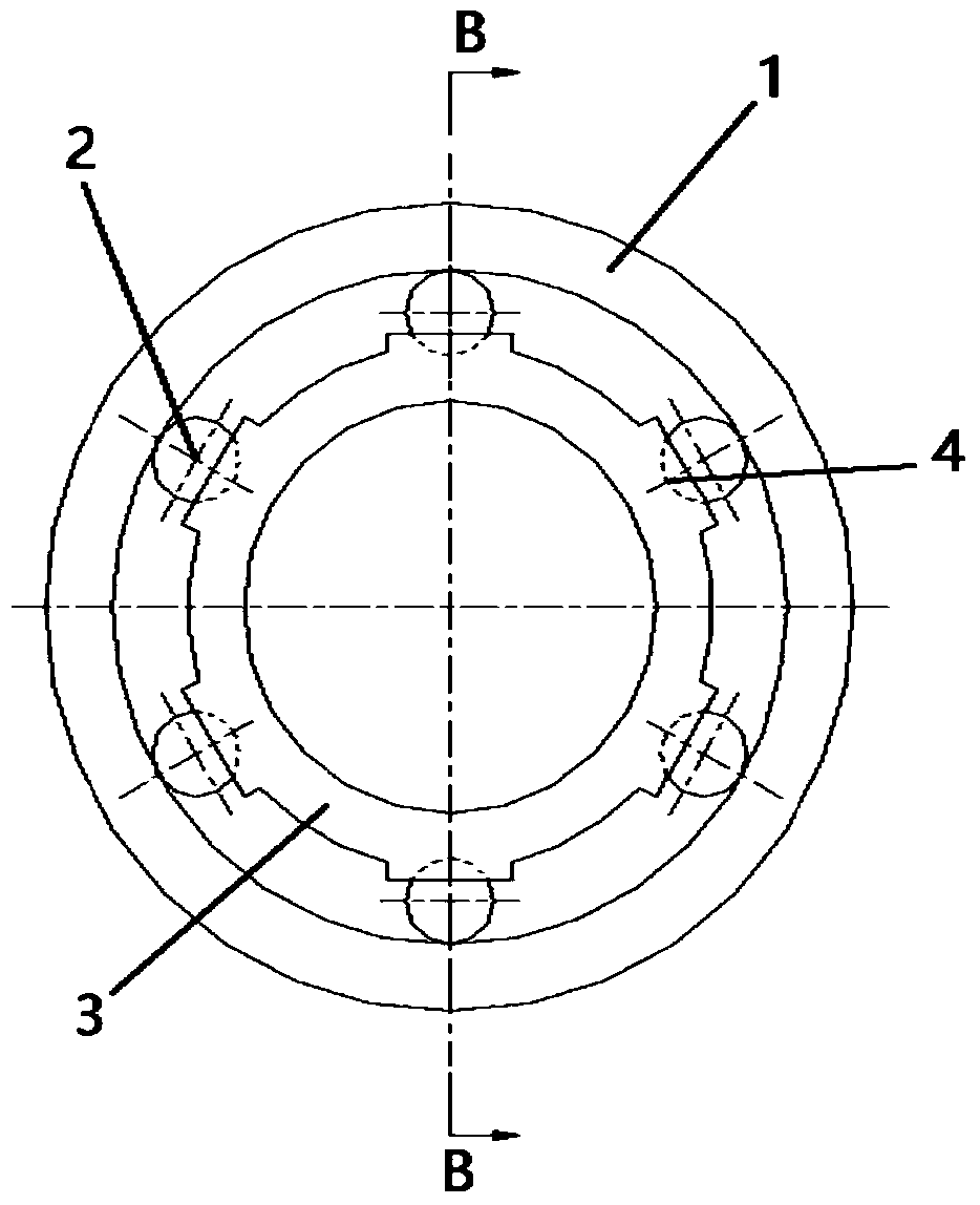
[0028] Aiming at the limitations of existing methods for preventing and controlling the slipping of aero-engine roller bearings, the present invention designs a rolling bearing that is especially suitable for the working conditions of aero-...


PUM


Abstract

The invention relates to a rolling bearing and an aero-engine. The rolling bearing comprises an outer circle, rolling elements, an inner circle and multiple roller paths which are circumferentially arranged on internal circumference of an outer circle or an external circumference of an inner circle at intervals, and each roller path is internally provided with one rolling element. Multiple roller paths which are circumferentially arranged on internal circumference of the outer circle of the rolling bearing or an external circumference of the inner circle at intervals are used for positioning the rolling elements, the roller paths limit the rolling elements as well as the inner circle or the outer circle, in order to guarantee synchronism of the rolling elements as well as the inner circle or the outer circle, and effectively prevent slip of the bearing; because interval positioning between rolling elements is realized by interval roller paths, so that holders are not needed to arrange, the structure is simple and reliable, weight is reduced, and running resistance of the rolling elements of the bearing is reduced at the same time; compared with common bearings, the quantity of the rolling elements is reduced to at least three, preload of the bearing is increased, and slip rate is reduced.

Description

technical field [0001] The invention relates to the technical field of aero-engines, in particular to a rolling bearing and an aero-engine. Background technique [0002] The working characteristics of roller bearings in aeroengines are high speed and small load. During high-speed operation, the rollers of the roller bearing tend to break away from the contact with the inner ring raceway under the action of a large centrifugal force. Because the rotors of aero-engines are made lighter, the radial load acting on the bearing is small, and when the aircraft is maneuvering, the radial load acting on the bearing will be smaller or even zero in some cases. At the same time, the unbalanced force of the rotor will offset some radial loads acting on the bearings in some cases, resulting in light or zero loads of the bearings. These two factors will make the drag force generated by the friction of the bearing become very small, or even zero. This will inevitably cause the bearing to...

Claims


Application Information

Patent Timeline
Patent Type & Authority Patents(China)
IPC IPC(8): F16C33/58
CPCF16C33/58
Inventor 梁霄朱希阁李琳任家海季寅泽
Owner AECC SHANGHAI COMML AIRCRAFT ENGINE MFG CO LTD
Why Eureka
Try Eureka