Dynamic clamping device for spinal implant

A technology for implants and spines, applied in spine implants, medical science, internal bone synthesis, etc., can solve the problems of elastic plastic rods that cannot be clamped in a durable way and reduce clamping force.

Inactive Publication Date: 2007-03-21
伯德比德尔曼股份公司
View PDF3 Cites 4 Cited by
  • Summary
  • Abstract
  • Description
  • Claims
  • Application Information

AI Technical Summary

Problems solved by technology

Therefore, elastic plastic rods cannot be clamped in a durable manner with a non-rig...

Method used


Image

  • Dynamic clamping device for spinal implant
  • Dynamic clamping device for spinal implant
  • Dynamic clamping device for spinal implant

Examples


Embodiment Construction

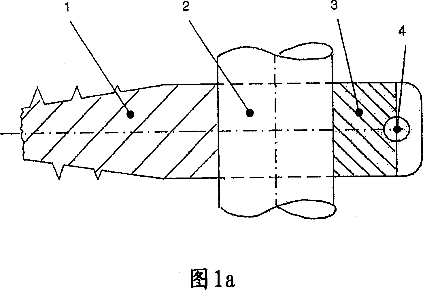
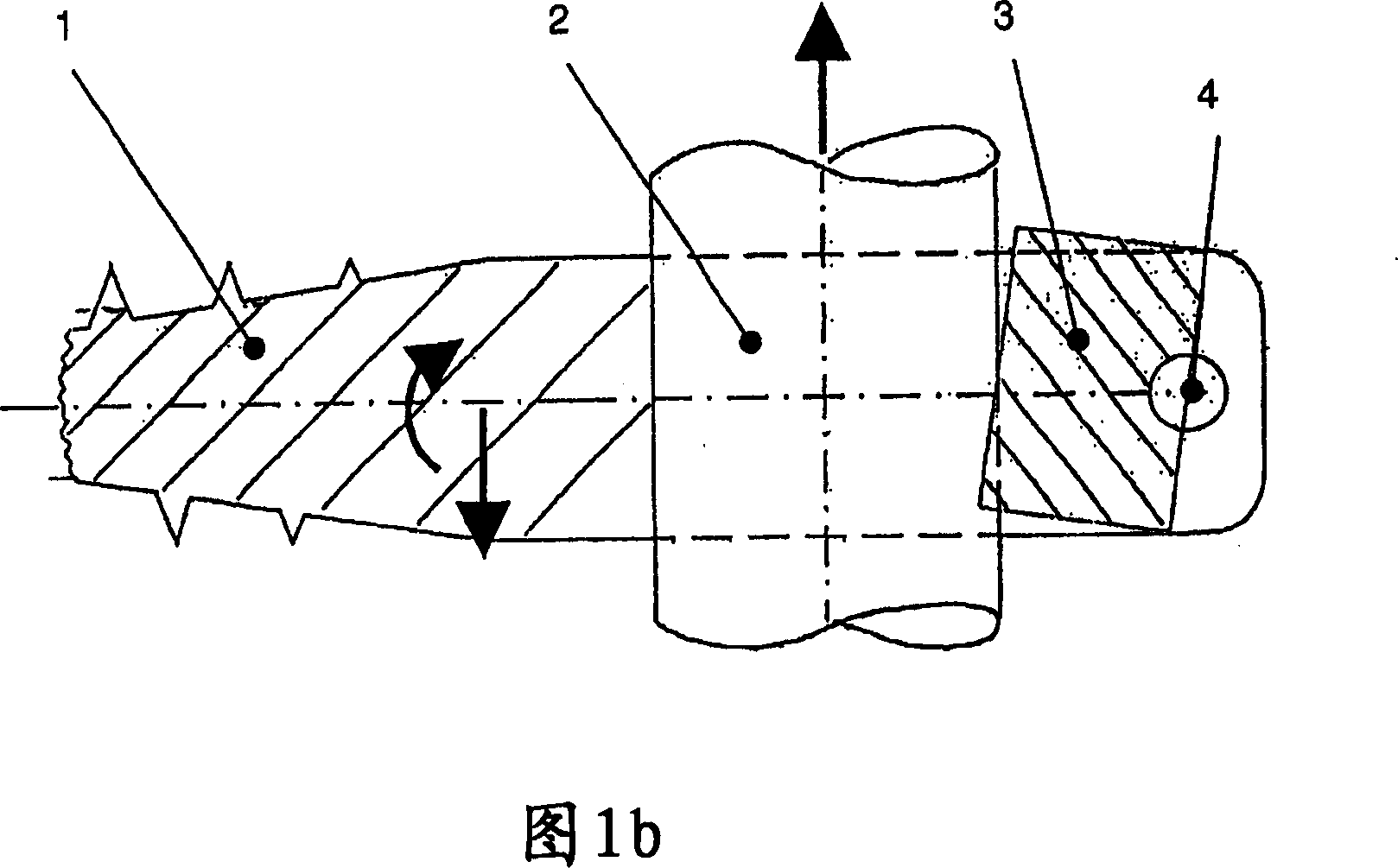
[0016] FIG. 1 a shows the elastic connection element 2 in a pedicle screw 1 (section) with the rotatable filler 3 in a neutral position relative to the fulcrum 4 . FIG. 1 b shows how the filling element 3 turns as soon as the elastic connecting element 2 is subjected to tension or stretching. Here, the filler piece 3 is arranged in such a way that its side opposite to the direction of the force presses against the surface of the elastic connecting element and creates a press-fit effect which significantly increases the anchoring force.

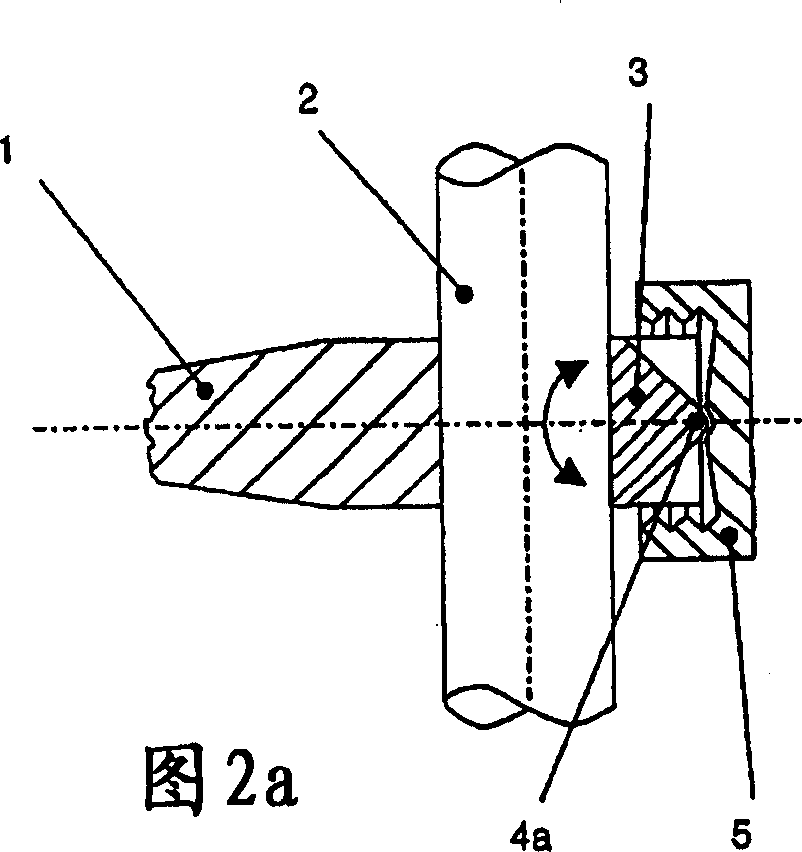
[0017] Figures 2a, 2b and 2c respectively show a side view, a front view and a top view of the elastic connection element 2, the pedicle screw 1, the filler piece 3 and the clamping element 5. Here, the clamping element 5 directly presses the rotatable filler 3 against the connecting element 2 via the spherical surface 4a.

[0018] Figures 3a, 3b and 3c respectively show a side view, a front view and a top view of the elastic connection eleme...


PUM


Abstract

To provide a spinal implant for stabilizing the vertebra bone by elasticity. An elastic rod is fixed to a receiving part of a stalk-like screw in a mode of non-forced engagement by a movable filling piece and a fixing element, and this non-forced engagement is additionally supported by contribution of dynamic engagement when load is applied.

Description

technical field [0001] The present invention relates to a dynamic stabilization system for the spine which stabilizes the spine without the need for spinal fusion. According to claim 1 of the invention, the elastic connecting element is connected in a novel way to the bone or to the pedicle screw. Background technique [0002] According to the prior art, various rod / screw connections are suitable for metal rods and are mainly used in fusion surgery (spinal fusion). There are only a few elastic systems that support and stabilize but do not fuse the spinal segments, and thus there are only a few devices for attaching elastic connecting elements to pedicle screws. [0003] In principle, rod / screw connections that are suitable for metal rods do not have to also be suitable for elastic connection elements, since for example elastic rods made of plastic have different properties than rods made of comparatively harder metal. Therefore, elastic plastic rods cannot be clamped in a ...

Claims


Application Information

Patent Timeline
IPC IPC(8): A61B17/70A61F2/00
CPCA61B17/7031A61B17/7032A61F2/44
Inventor S·弗洛伊迪格
Owner 伯德比德尔曼股份公司
Why Eureka
Try Eureka