Rail table system

A trolley system and trolley technology, applied in the system field, can solve problems such as cost increase and inability to solve stop accuracy

Inactive Publication Date: 2007-03-21
MURATA MASCH LTD
View PDF0 Cites 13 Cited by
  • Summary
  • Abstract
  • Description
  • Claims
  • Application Information

AI Technical Summary

Problems solved by technology

LIM cannot solve the problem of stopping accuracy, and if it is replaced by a linear synchronous motor (LSM), it will cause cost problems
For example, the control of LSM requires a linear sensor that can detect the position of the trolley, but if the linear sensor is installed along a long travel path, its cost will increase significantly

Method used


Image

  • Rail table system
  • Rail table system
  • Rail table system

Examples


Embodiment

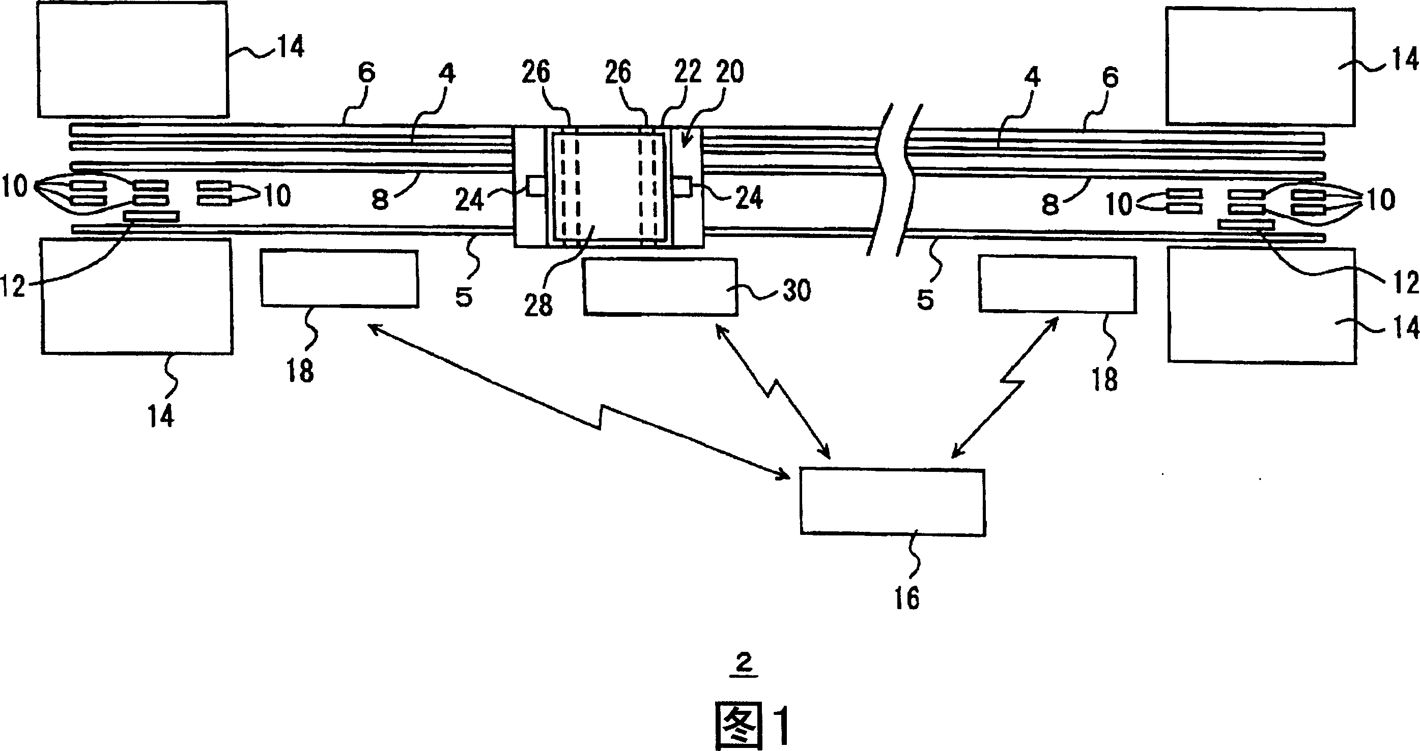
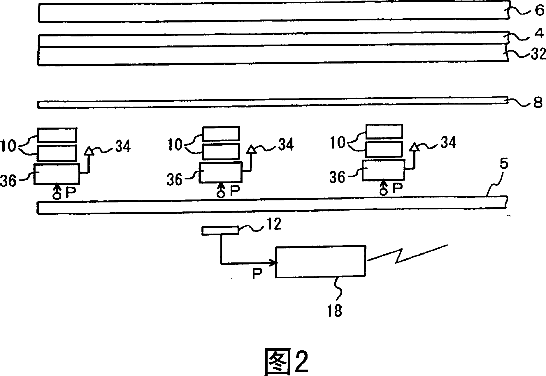
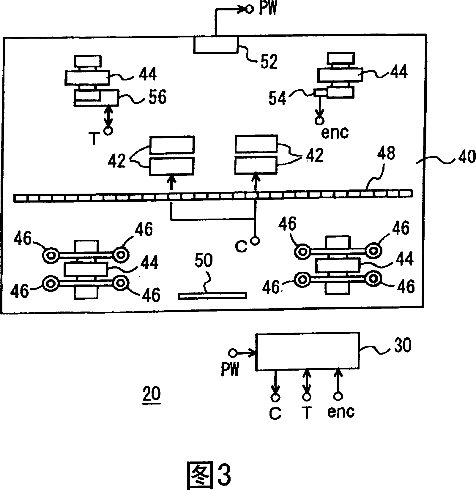
[0024] 1 to 8 show the embodiment and its modifications. In the figure, 2 is a trolley system, which can be regarded as a system for transporting boxes containing multiple liquid crystal substrates in a clean room. 4 and 5 are running rails, 6 is a power supply rail for non-contact power supply, 8 is a secondary conductor of a linear induction motor (LIM), and 10 is a primary coil of a linear synchronous motor (LSM). 12 is an ABS linear sensor, which detects the absolute position of the stacking crane 20 relative to the stop position of the docking station 14 , and 16 is a control unit, which controls the entire rail trolley system 2 . Also, 18 is a docking station control unit, which controls the primary coil 10 and the like of the linear synchronous motor using signals from the ABS linear sensor 12 and the like.

[0025] 20 is a stacking crane, 22 is a lifting platform, which moves up and down along the mast 24, and uses a transfer mechanism 26 such as a sliding fork to tra...


PUM


Abstract

This invention provided a track mounted jumbo systerm. In this system, a primary coil (10) of a linear synchronous motor is arranged at the fixing side in the vicinity of a station, and a magnet row (48) of the linear synchronous motor is arranged at a stacker crane (20). A primary coil (42) of a linear induction motor is arranged at the stacker crane (20), and a secondary conductor (8) is continuously arranged between the stations at the fixing side. The power of the linear induction motor is obtained from a non-contact electricity receiving part (52) by supporting the weight of the stacker crane (20) by a traveling wheel (44), and by supporting swiveling forces acting from the linear induction motor and the linear synchronous motor by a guide roller (46). The primary coil (10) is operated in the vicinity of the station by detecting a magnet position in the magnet row (48), and stopped by detecting an absolute position of the stacker crane (20) with respect to the station by an ABS linear sensor (12).

Description

technical field [0001] The invention relates to systems such as stacking cranes or bridge cranes, rail trolleys traveling on the ground and the like. Background technique [0002] We have already known a trolley system that uses a linear induction motor (LIM) to drive a trolley in a clean room or the like. The trolley system requires the trolley to travel at high speed over a long travel distance and to improve the accuracy of the stop position. LIM cannot solve the problem of stopping accuracy, and if a linear synchronous motor (LSM) is used instead, a problem of cost will arise. For example, the control of the LSM requires a linear sensor capable of detecting the position of the trolley, but if the linear sensor is installed along a long travel path, its cost will increase significantly. Contents of the invention [0003] The object of the present invention is to use a simple system to enable rail trolleys to be transported over long distances, at high speeds, and with...

Claims


Application Information

Patent Timeline
Patent Type & Authority Applications(China)
IPC IPC(8): B60L13/03
Inventor 鸳海幸一郎石川和广
Owner MURATA MASCH LTD
Why Eureka
Try Eureka