Microleak automatic protection apparatus based on microflow detection

An automatic protection, micro-flow technology, used in measuring devices, fluid velocity measurement, fluid tightness testing, etc., can solve the problems of low safety, short effective service life, pipeline influence, etc. High detection accuracy and small footprint

Active Publication Date: 2010-05-12
ACEINNA TRANSDUCER SYST CO LTD
View PDF7 Cites 0 Cited by
  • Summary
  • Abstract
  • Description
  • Claims
  • Application Information

AI Technical Summary

Problems solved by technology

[0004] The present invention mainly solves the problems existing in the prior art that it is easily affected by various factors. It can only alarm when the gas leaks and reaches a certain concentration. The technical problems such as the occurrence of accidents and low safety; provide a reasonable design, simple structure, small space occupation, high detection accuracy, no interference from external factors, real-time monitoring of pipeline conditions, and automatic cutoff in case of danger. Micro-leak automatic protection device and method based on micro-flow detection
[0005] Another purpose of the present invention is to solve the technical problems existing in the prior art that the equipment cost is high, the effective service life is short, and it is easy to cause failure in fact and the user is negligent in management and cannot detect it, but there are greater safety hazards. Provides a micro-leakage automatic protection device based on micro-flow detection and its method with low cost, long effective service life, high working stability, and users can use it with confidence without worrying about failure
[0006] Another purpose of the present invention is to solve the technical problems in the prior art that the monitoring sensitivity is not high, the slight leakage cannot be detected in time, and the impurities in the pipeline are easy to affect the monitoring; a branch circuit structure is provided. In the state of the same flow rate, the fluid speed can be effectively increased, the sensor has high sensitivity, and the impurities in the pipeline will not block the branch, so as to ensure safe and smooth micro-leakage automatic protection device and method based on micro-flow detection

Method used


Image

  • Microleak automatic protection apparatus based on microflow detection
  • Microleak automatic protection apparatus based on microflow detection
  • Microleak automatic protection apparatus based on microflow detection

Examples


Embodiment 1

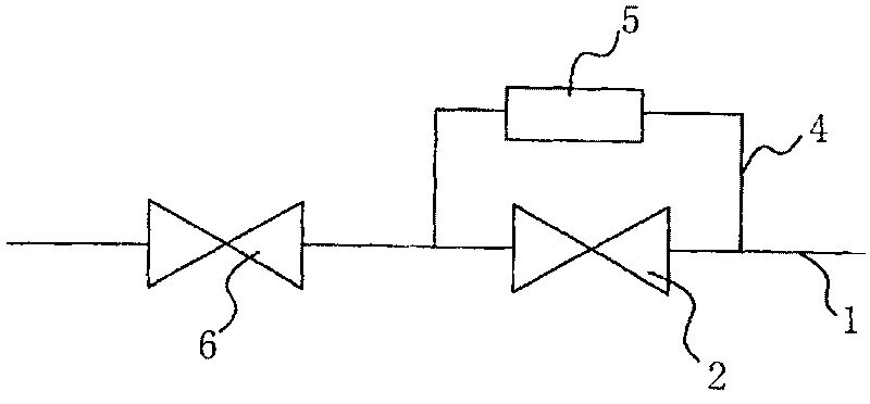
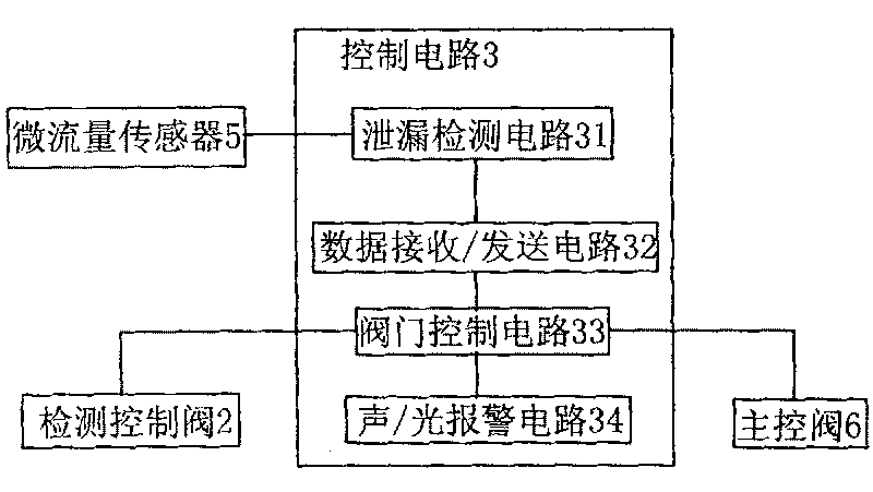
[0029]Such as figure 1 and figure 2 As shown, the automatic protection device for micro-leakage based on micro-flow detection is set on the delivery pipeline. It consists of a micro flow sensor 5, a control circuit 3, a detection channel 4, a detection control valve 2, a main control valve 6 and other components.

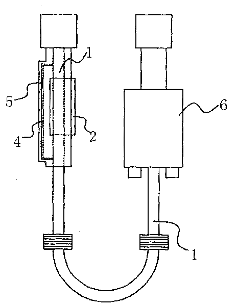
[0030] Such as image 3 As shown, the detection control valve 2 is installed on the main pipeline 1, and the control circuit 3 is connected with the detection control valve 2. The main pipeline 1 is connected with a detection channel 4 whose diameter is much smaller than that of the main pipeline 1 . The two ends of the detection channel 4 are respectively located at the two ends of the detection control valve 2 . A micro-flow sensor 5 is arranged in the detection channel 4 , and the micro-flow sensor 5 is connected with the control circuit 3 . The detection channel 4 and the main pipeline 1 are arranged on the same pipe, the detection channel 4 is located on t...

Embodiment 2

[0037] Such as Figure 5 As shown, in this embodiment, the detection channel 4 is located on the outer wall of the main pipeline 1, that is, a channel is opened outside the pipeline, and the rest are the same as in the embodiment 1, which will not be repeated here.

Embodiment 3

[0039] In this embodiment, the detection channel 4 is in the shape of a circular tube, and a flat channel 41 is arranged in the middle thereof, and the micro flow sensor 5 is arranged on the inner wall of the flat channel 41 . That is, a passage is opened in the pipeline, and the rest are the same as those in Embodiment 1 or 2, and will not be described in detail herein.


PUM


Abstract

This invention relates to a micro-leakage automatic protection device based on micro-flow test and a method, in which, the device is set on a duct including a test control valve on a main pipeline anda control circuit connected with the test control valve characterizing that a test channel is connected on the main pipeline with the diameter far smaller than that of the main one, both ends of thetest channel are at both ends of the control valve, a micro-flow sensor is set in the channel connected with the control circuit.

Description

technical field [0001] The invention relates to the field of safety protection, in particular to an automatic protection device for micro-leakage based on micro-flow detection and a method thereof. Background technique [0002] Combustible gases such as liquefied petroleum gas, coal gas, and natural gas have increasingly become the most important fuels for households. However, due to pipeline aging, quality defects and other reasons, flammable gases often leak. Because the leakage of gas is not easy to be found, it often causes accidents such as poisoning, fire, explosion, personal injury and death. In order to prevent the occurrence of such accidents, people have carried out long-term exploration and proposed various implementation schemes. However, when common gas alarms leak, they can only report to the police when the gas leaks to a certain concentration. Obviously, the detection of gas concentration is related to many factors, such as the degree of gas convection, th...

Claims


Application Information

Patent Timeline
Patent Type & Authority Patents(China)
IPC IPC(8): F24C3/12G01P5/00G01M3/00
Inventor 毛巨林赵文宏金耀青
Owner ACEINNA TRANSDUCER SYST CO LTD
Why Eureka
Try Eureka