Evaluating the position of disturbance

A motion and interferometer technology, applied in the direction of measuring devices, testing of machine/structural components, using optical devices to transmit sensing components, etc., can solve problems such as not being well applicable

Active Publication Date: 2007-03-28
BRITISH TELECOMM PLC
View PDF0 Cites 14 Cited by
  • Summary
  • Abstract
  • Description
  • Claims
  • Application Information

AI Technical Summary

Problems solved by technology

However, this known optical time domain reflectometry (OTDR) technique is not well suited for detecting time-varying disturbances

Method used


Image

  • Evaluating the position of disturbance
  • Evaluating the position of disturbance
  • Evaluating the position of disturbance

Examples


Embodiment Construction

[0032] Estimate the location of the disturbance

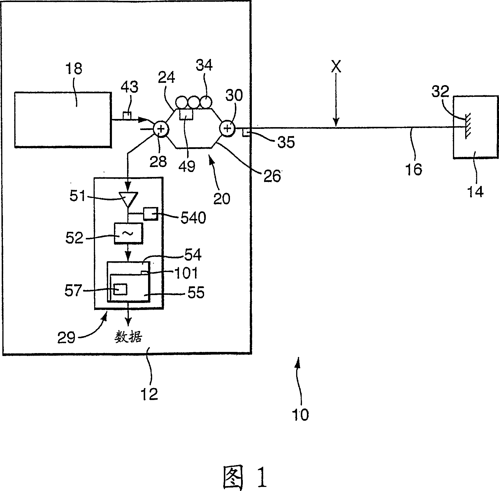
[0033] FIG. 1 shows a detection system 10 in which a monitoring station 12 is connected to an optical fiber 16 . A dynamic perturbation is introduced at a point marked X on the fiber, the position of which along the fiber is to be determined. In general terms, the monitoring station 12 is configured to transmit onto the optical fiber 16 detection signals which undergo phase changes due to dynamic perturbations. A component of the detected signal is returned due to Rayleigh backscattering along the fiber. The backscattered components returned to the monitoring station 12 are then processed to discern phase changes introduced by dynamic perturbations. Since the backscatter components returning from different regions of the fiber arrive at the monitoring station 12 at different times, the location of the disturbance is determined from the return time of the modulated backscatter components.

[0034] The monitoring station 12 co...


PUM


Abstract

The present invention relates to a method of and apparatus for evaluating the position of a disturbance on an optical link, in particular where the disturbance is a time-varying disturbance. An optical time domain reflectometry technique is used in which a series of low coherence test pulses is launched by means of an optical pulse source (18) into an the optical link (16), and the backscattered return signal is monitored. The test pulses pass through an unbalanced Mach Zhender interferometer (20) with the result that for each test pulse, a pair of time-displaced pulse copies is launched onto the link (16). The backscattered return signal is passed through the same interferometer (20), which causes the pulse copes of each pair to become realigned and to interfere with one another. A time-varying disturbance (x) is likely to affect each pulse copy of a pair differently. As a result, an abnormality such as a step is likely occur in the backscattered signal. From the time position of an abnormality, the distance of the disturbance responsible is evaluated.

Description

technical field [0001] The present invention relates to a method and a device for estimating the position of a disturbance on a transmission link, in particular to a method and a device for estimating the position of a disturbance on a transmission link if the disturbance is a time-varying disturbance. Background technique [0002] It is known that irregularities can be estimated by launching a test pulse in a waveguide and monitoring the distributed backscattering of the test pulse to detect anomalies, if any, in the returning, time-correlated signal (irregularity) position in the waveguide. An example of an anomaly may be a time-dependent step change in the amplitude of the return signal. However, this known optical time domain reflectometry (OTDR) technique is not well suited for detecting time-varying disturbances. Contents of the invention [0003] According to the invention there is provided a method of estimating the position of a time-varying disturbance on a tra...

Claims


Application Information

Patent Timeline
Patent Type & Authority Applications(China)
IPC IPC(8): G01M11/00G01D5/353
CPCG01M11/3172G01D5/35303G01M11/00
Inventor 彼得·希利埃德蒙·塞尔焦·罗伯特·希科劳
Owner BRITISH TELECOMM PLC
Why Eureka
Try Eureka