Finial seat

A technology of top seat and top shaft, which is applied in the direction of tailstock/top, turning equipment, tool holder accessories, etc. It can solve problems such as difficult operation, difficult operation of piezoelectric elements, and damage to the concentricity of the top shaft, so as to suppress micro-vibration , The effect of maintaining machining accuracy

Active Publication Date: 2010-05-12
TSUDAKOMA KOGYO KK
View PDF7 Cites 0 Cited by
  • Summary
  • Abstract
  • Description
  • Claims
  • Application Information

AI Technical Summary

Problems solved by technology

Therefore, when the piezoelectric element that the tip shaft is strongly in contact with quickly wears out, and the wear exceeds the allowable amount, the concentricity between the tip shaft and the lathe or indexing table, etc. will be destroyed, and the tip cannot be sufficiently pressed during processing. shaft, so replacement is necessary
[0007] However, since the piezoelectric element is installed in the groove formed in the through hole of the main body, it is difficult to replace the piezoelectric element, and when replacing it, it is necessary to pay great attention not to damage the wires that apply voltage to the piezoelectric element. From a point of view, the operation of replacing the piezoelectric element is also difficult

Method used


Image

  • Finial seat
  • Finial seat
  • Finial seat

Examples


Embodiment Construction

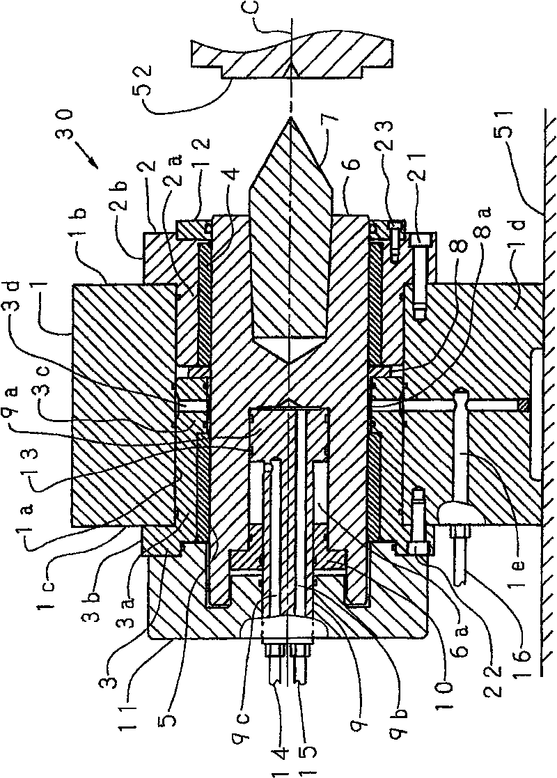
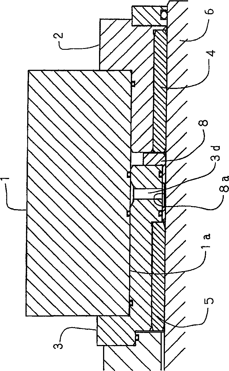
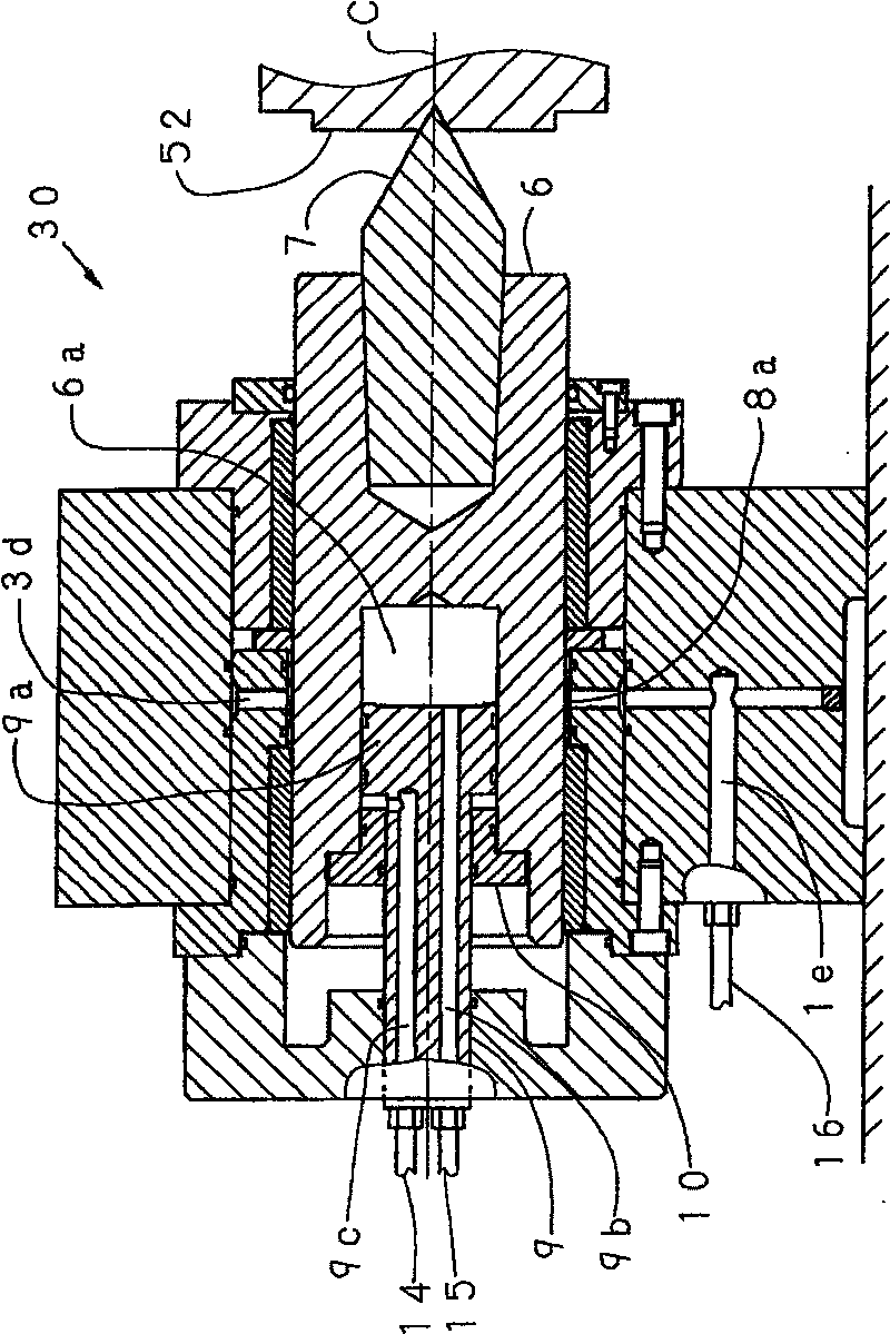
[0023] Hereinafter, embodiments of the present invention will be described with reference to the drawings. Figure 1 ~ Figure 3 Shown is a sectional view of the center seat 30 of the first embodiment of the present invention, figure 1 and image 3 Respectively indicate the state of the top axis when it is most retreated and when it is advanced, figure 2 yes figure 1 An enlarged view of the main part.

[0024] The top seat 30 of the present embodiment has a main body 1, a bearing cage 2, a shaft 6, a top 7, a plunger 9, a plunger guide sleeve 10, pipelines 14, 15, 16, a clamping ring 8, a front side cover 12 and Rear side cover 11.

[0025]The main body 1 has a through hole 1a and a base portion 1d. The base portion 1d is fixed on the slide rail 51 of the machine tool and faces the workpiece 52 held on the main shaft of the machine tool or the index table (not shown). The oil-impregnated bearing 4 is fitted into the inner peripheral surface of the bearing holding part 2a,...


PUM


Abstract

The present invention provides a tailstock which securely clamps a tailstock barrel in working to prevent the barrel from chattering for keeping working accuracy of a workpiece and also enables a bearing member of the tailstock barrel to be easily replaced when the member has worn. The tailstock comprises a body having a through-hole, the tailstock barrel inserted into the through-hole and slidably and rotatablely supported, and a fluid pressure driver for driving the tailstock barrel to be pressed against the workpiece. The tailstock is equipped with a pair of bearing members which can be inserted between the through-hole and the tailstock barrel respectively from the side of the workpiece and the side opposite to the workpiece and axially separate from each other, and also equipped witha clamping device. The clamping device includes a hollow member provided to surround the tailstock barrel between the pair of bearing members and a high pressure fluid supplying device for supplying ahigh pressure fluid to an internal space of the hollow member. The hollow member is fixed to the body and also has a radially inward part pressing the tailstock barrel with an inflow of the high pressure fluid so as to clamp the tailstock barrel.

Description

technical field [0001] The invention relates to a top seat (core pressing platform), which is set facing the main shaft of a lathe or an indexing workbench, and presses one end tightly against the other end of a workpiece held on the lathe or an indexing workbench, so as to suppress the workpiece from being generated by the machining force. The displacement of the workpiece maintains the machining accuracy of the workpiece. Background technique [0002] The top seat is set facing the main shaft of the lathe or the indexing table, and the top shaft is pushed forward and pressed against the other end of the workpiece held on the lathe or the indexing table. Therefore, the other end of the workpiece is supported by the tip shaft, which suppresses displacement due to machining force and maintains machining accuracy. [0003] However, since the tip shaft is slidably and rotatably supported by the frame of the tip base, that is, the main body, an appropriate gap must be provided ...

Claims


Application Information

Patent Timeline
Patent Type & Authority Patents(China)
IPC IPC(8): B23B23/00
Inventor 多田裕之
Owner TSUDAKOMA KOGYO KK
Why Eureka
Try Eureka