motor control unit

A control device and motor technology, applied in the direction of AC motor control, control system, electrical components, etc., can solve the problems of large leakage current, micro vibration of motor output shaft, etc., and achieve the effect of suppressing micro vibration

Active Publication Date: 2019-06-18
PANASONIC INTELLECTUAL PROPERTY MANAGEMENT CO LTD
View PDF6 Cites 0 Cited by
  • Summary
  • Abstract
  • Description
  • Claims
  • Application Information

AI Technical Summary

Problems solved by technology

In particular, when the current flowing through the motor is small and the switching timing of each phase tends to overlap during servo lock or low-speed operation, the influence of the leakage current is relatively large.
Therefore, for example, there is a problem that even during servo lock when the motor output shaft should be in a stationary state, microvibration of the motor output shaft due to unnecessary torque occurs.

Method used


Image

  • motor control unit
  • motor control unit
  • motor control unit

Examples


Embodiment approach

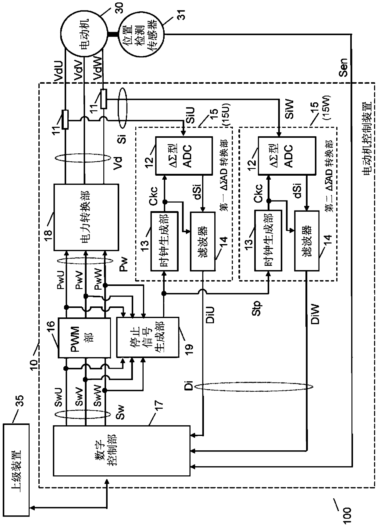
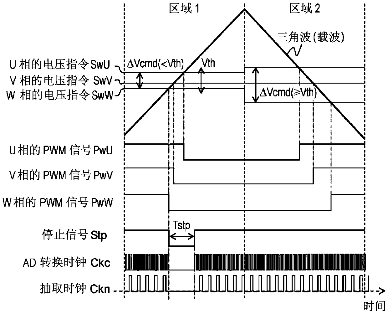
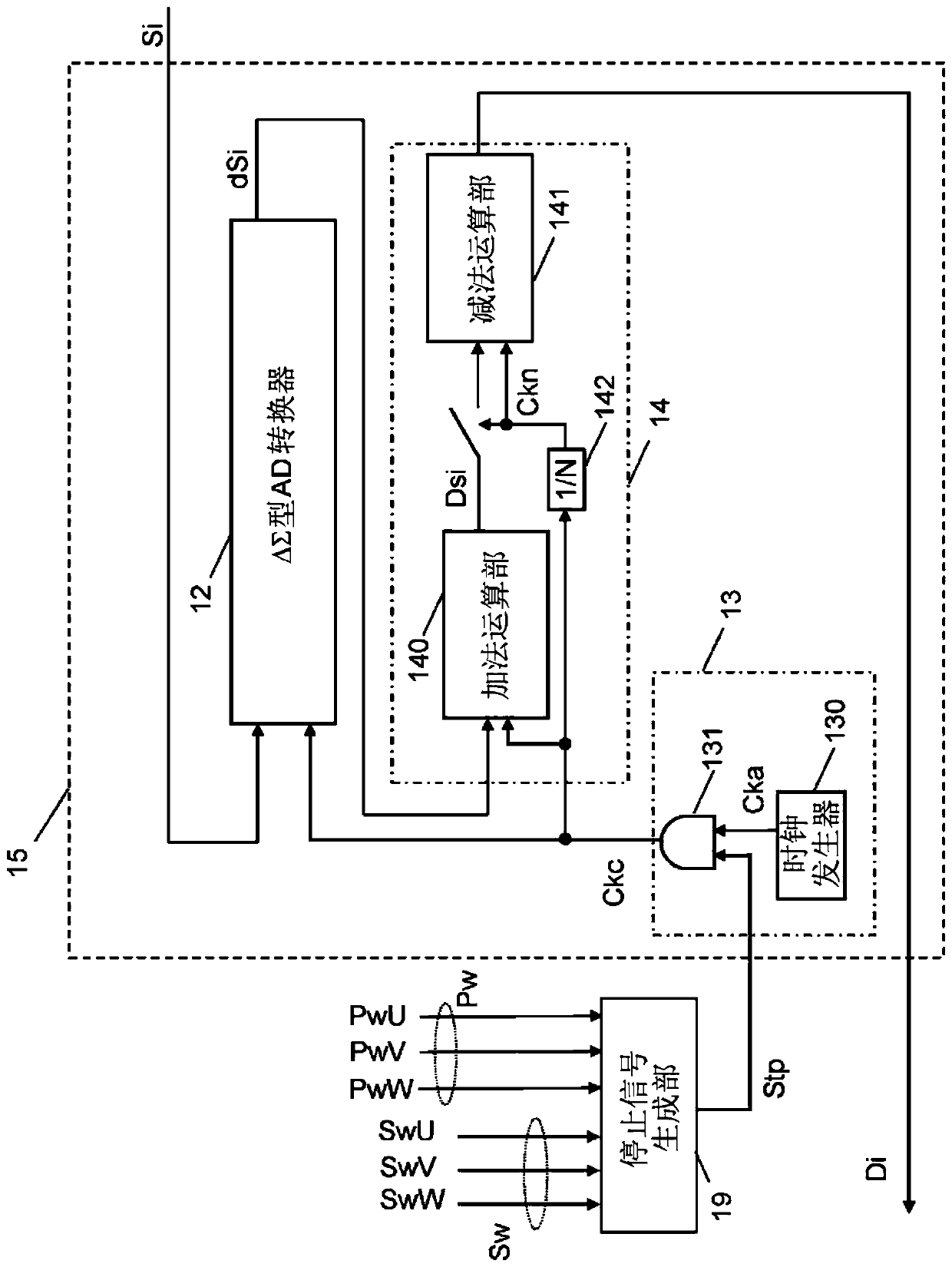
[0017] figure 1 is a configuration diagram of a motor control system including a motor control device in an embodiment of the present invention, figure 2 It is an operation waveform diagram for explaining the operation of the ΔΣAD converter used for detecting the motor current, image 3 This is a block diagram of the ΔΣAD converter that detects the motor current.

[0018] Such as figure 1 As shown, the present motor control system 100 is configured such that the motor control device 10 controls the operation of the motor 30 according to the instruction control of the host device 35 .

[0019] The host device 35 is constituted by, for example, a personal computer or the like, and controls the motor control device 10 by commands or the like. The host device 35 is communicably connected to the motor control device 10 via a control bus or the like. Commands from the host device 35 are transmitted to the motor control device 10 and information from the motor control device 10...


PUM


Abstract

This motor control device controls the operation of a motor and comprises a motor current detection unit for detecting current that flows through a winding in a motor provided with a stator having a three-phase winding wound therearound. The motor control device is provided with: a digital control unit that calculates a voltage command value for driving the motor; a PWM unit that outputs a PWM switching signal by pulse width modulation; a power conversion unit that applies drive voltage to the winding in accordance with the PWM switching signal; a current detection unit that uses the drive voltage to detect current that flows through the winding; a ΔΣ A / D conversion unit that converts the detected current amount into a digital signal; and a stop signal generation unit that outputs a stop signal for stopping operation of the ΔΣ A / D conversion unit. In addition, when the difference between the maximum value and the minimum value of the voltage command is equal to or less than a predetermined threshold value, the stop signal generation unit outputs the stop signal for a predetermined length of time.

Description

technical field [0001] The present invention relates to a motor control device that freely controls the motor by applying a driving voltage generated by PWM control to the winding of the motor to control the flowing current, and more particularly relates to a motor control device that detects the voltage generated by applying the driving voltage to the winding. A motor control device that is a function of the current value. Background technique [0002] In a servo motor used in FA (Factory Automation), the position, speed, and torque of the motor are controlled so as to follow a drive command (position command) from a host device (host controller). Furthermore, digital control using a microprocessor is widely used as the control computing means. The torque output by the surface permanent magnet synchronous motor (Surface Permanent Magnet Synchronous Motor) used in the servo motor has a proportional relationship with the motor current. Therefore, the current value of the mot...

Claims


Application Information

Patent Timeline
Patent Type & Authority Patents(China)
IPC IPC(8): H02P27/06
CPCH02P27/06
Inventor 增田隆宏岸部太郎
Owner PANASONIC INTELLECTUAL PROPERTY MANAGEMENT CO LTD
Why Eureka
Try Eureka