
Axial-displacement cutter carriage structure of miller

A milling device and axial displacement technology, applied in positioning devices, milling machine equipment, details of milling machine equipment, etc., can solve the problem of not being able to simultaneously mill holes, hole holes or drilling, waste of energy resources, and load on the spindle and its helical gears. Heavy and other problems to achieve the effect of improving operation convenience and work efficiency

Inactive Publication Date: 2007-04-04
王主机械厂有限公司
View PDF0 Cites 3 Cited by
  • Summary
  • Abstract
  • Description
  • Claims
  • Application Information

AI Technical Summary

Problems solved by technology

[0005] 1. Although the sliding seat 36 of the previous case 1 can drive the turning tool holder 4 to move up and down to adjust the height of the turning tool, its structure is only used for lathes, and it can only be used for lathe processing and cannot simultaneously have milling holes, gallium holes or Drilling and other functions have low applicability and do not meet the needs of the industry for construction efficiency
[0006] 2. Although the motor in the previous case 2 can drive the main shaft to drive the cutter holder, since the helical gear of each main shaft needs to drive three sets of helical gears of the cutter holder at the same time, not only the load on the main shaft and its helical gear is too heavy, but also the main shaft The transmission force of the helical gear is scattered, so that the cutter holder cannot perform heavy cutting work
[0007] 3. When the main shaft of the previous case 2 rotates, its upper, middle and lower helical gears simultaneously drive the three axial tool holders on the left, right and front to rotate. However, in the actual processing process, whether it is drilling or Milling is only used on one of the axial tools, and the other two axial tool holders are basically in an idling state, resulting in a waste of energy resources

Method used


Image

  • Axial-displacement cutter carriage structure of miller
  • Axial-displacement cutter carriage structure of miller
  • Axial-displacement cutter carriage structure of miller

Examples


Embodiment Construction

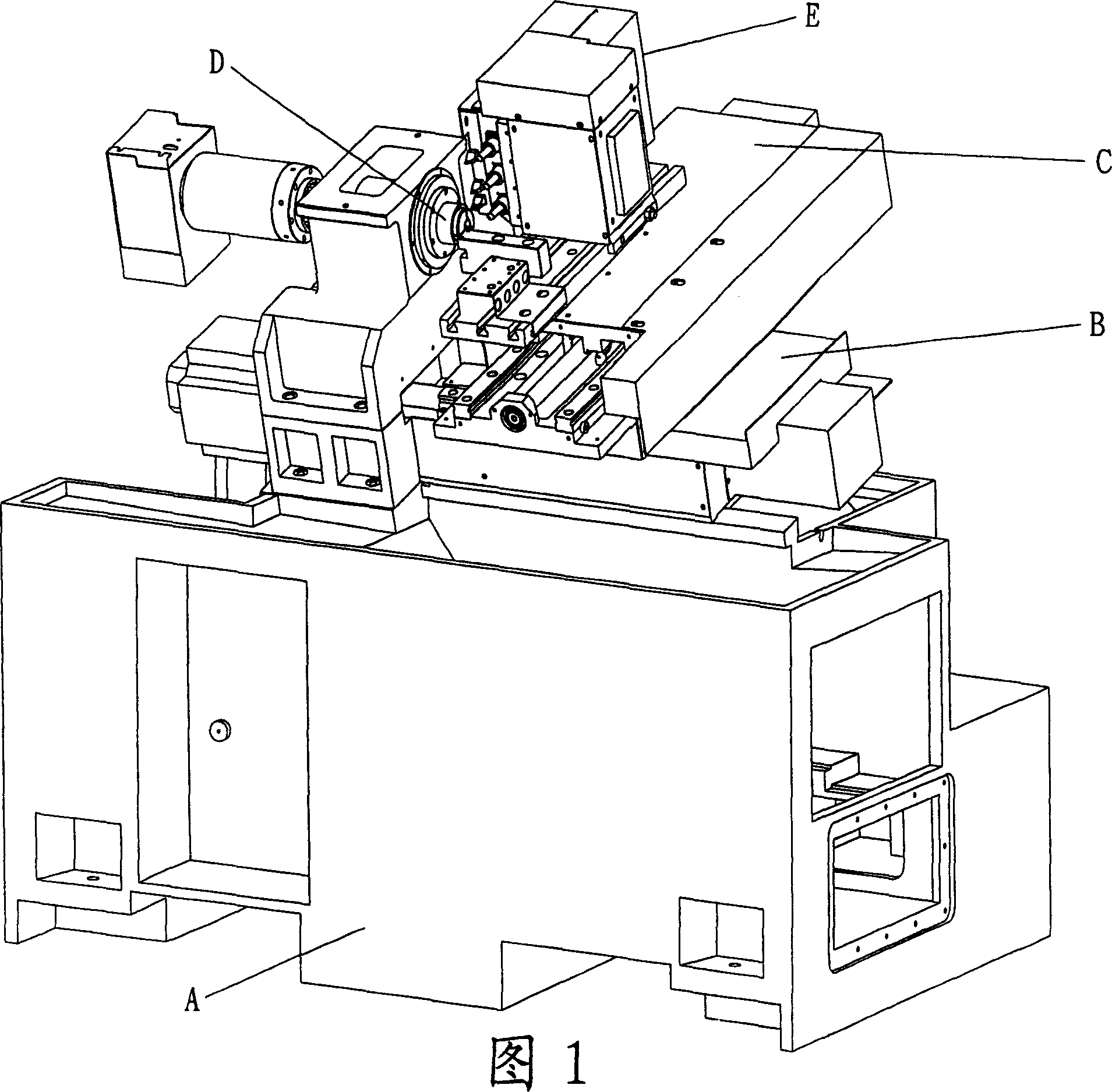
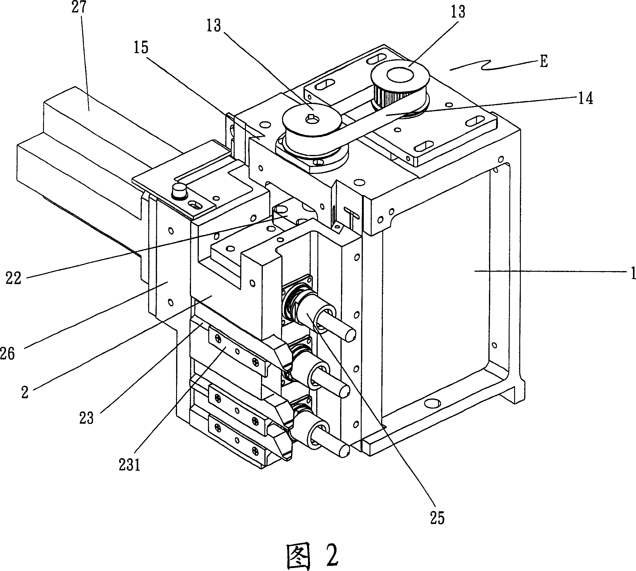
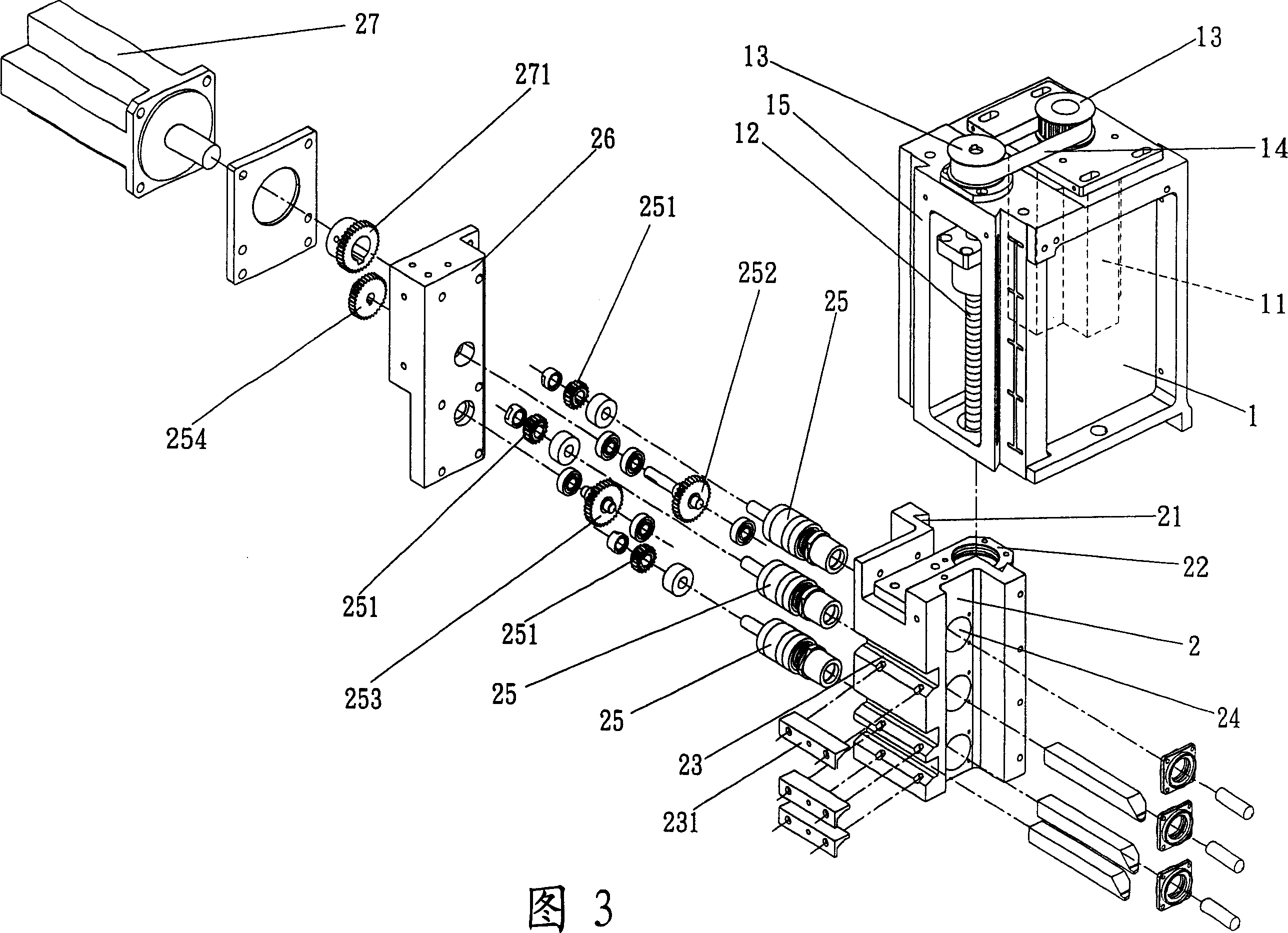
[0021] First please refer to Fig. 1 and Fig. 2, the CNC automatic processing machine of the present invention mainly includes machine table A, on which machine table A is provided with transverse sliding mechanism B, longitudinal sliding mechanism C, and a group of fixed and clampable Workpiece fixture D for high-speed rotation, and a group of milling device E (please refer to Figure 2) erected above the longitudinal sliding mechanism C; next, please cooperate with Figure 3 and Figure 4, the milling device E of the present invention mainly It includes a base 1 and a knife holder 2, wherein:

[0022] The base 1, as shown in Figure 3, is a rectangular inner hollow body, the base 1 is provided with a base motor 11 and a ball screw 12, and the gear 13 and the belt 14 on the top surface of the base 1 are used for transmission between the two. , and the base 1 is formed with a longitudinal dovetail slide rail 15 on the side facing the workpiece fixture D;

[0023] As shown in Figur...


PUM


Abstract

A tool carrier structure able to move axially for the milling machine with milling, boring, drilling and turning functions is composed of a base, a tool carrier able to axially lift and consisting of a main body with several through holes, the drill bit holders in said through holes (one in one), drive gears for said drill bit holders (one for one) and the second and the third guide gears engaged with said drive gears for making the drill bit holders to rotate synchronously, and a carrier motor as the power source.

Description

technical field [0001] The present invention relates to a novel tool holder structure capable of axial displacement in a milling device, in particular to a milling device with multiple functions such as milling, milling, drilling and turning, and the tool of the milling device The frame can be displaced axially up and down to facilitate the use of different tools in the same process. Background technique [0002] After a long period of technological development and continuous improvement, the CNC processing machine industry has become the mainstream equipment for domestic machining, and the general CNC processing machine is equipped with a set of milling devices for processing workpieces. The milling device usually includes a set of For the base that can be displaced horizontally, horizontally and vertically relative to the workpiece, and a set of tool holders for tool installation, for the structure of traditional milling devices, please refer to Announcement No. 356373 (he...

Claims


Application Information

Patent Timeline
Patent Type & Authority Applications(China)
IPC IPC(8): B23Q3/155B23C9/00
Inventor 王家丁
Owner 王主机械厂有限公司
Learn More