Yarn feeder

A yarn feeder and container technology, applied in thin material processing, textiles and papermaking, looms, etc., can solve problems such as tedious bonding process, impossible height adjustment of storage surface, and difficulty in leveling, etc., to improve self-locking The effect of the function

Inactive Publication Date: 2007-04-04
IRO AB
View PDF2 Cites 2 Cited by
  • Summary
  • Abstract
  • Description
  • Claims
  • Application Information

AI Technical Summary

Problems solved by technology

The bonding process is tedious and time consuming
Furthermore, it is difficult to precisely align the upper surface of the reflector with respect to the adjacen

Method used


Image

  • Yarn feeder
  • Yarn feeder
  • Yarn feeder

Examples


Embodiment Construction

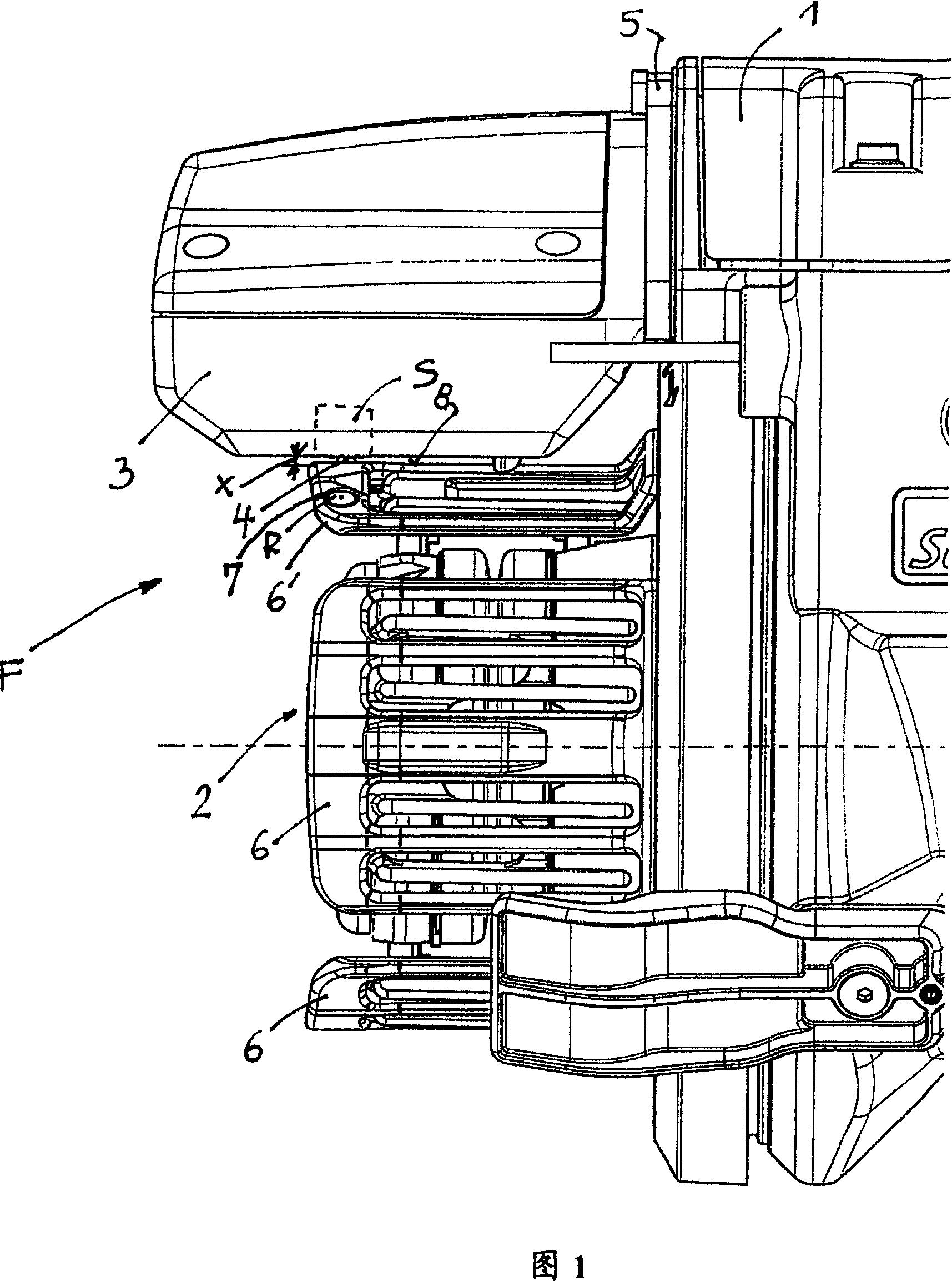
[0025] The present invention will explain a so-called measuring yarn feeder of a jet loom. However, the measuring yarn feeder is only chosen as an example. Alternative reflector body fixing principles can be used in other types of yarn feeders, eg for other types of textile or weaving machines or similar.

[0026] In FIG. 1 , the measuring yarn feeder comprises a housing 1 , a fixed storage body 2 and a brake housing 3 . The fixed storage volume 2 has a variable diameter. In order to adjust the radial position of the brake housing 3, once the predetermined diameter of the storage body 2 is adjusted, the brake housing 3 is adjustable in the radial direction relative to the axis of the storage body 2, so that in the storage of the storage drum 2 (storage drum) The yarn passing gap X between the surface 8 and the brake housing 3 usually has a certain width. This measurement is usually done with a gap gauge G (Figure 4).

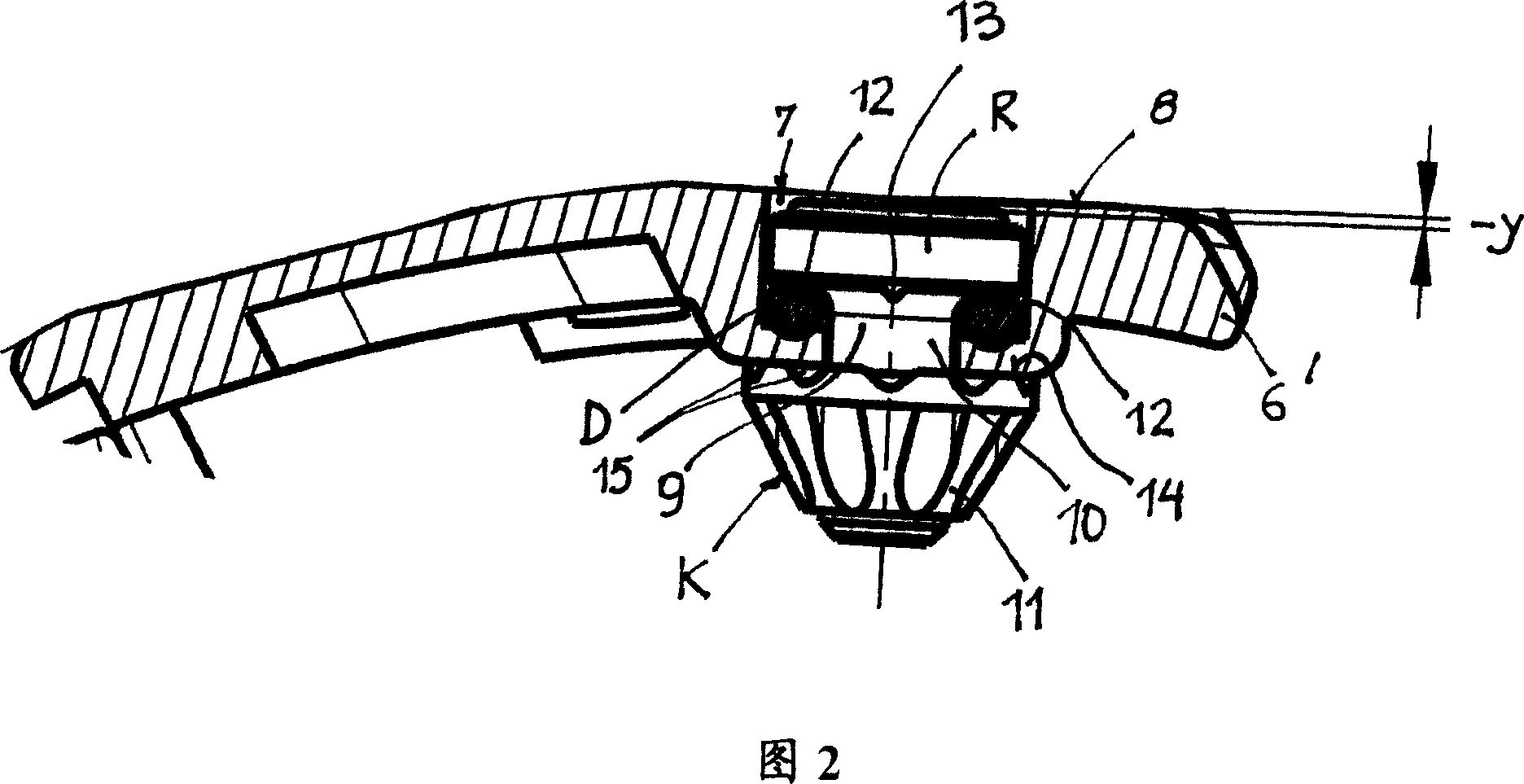
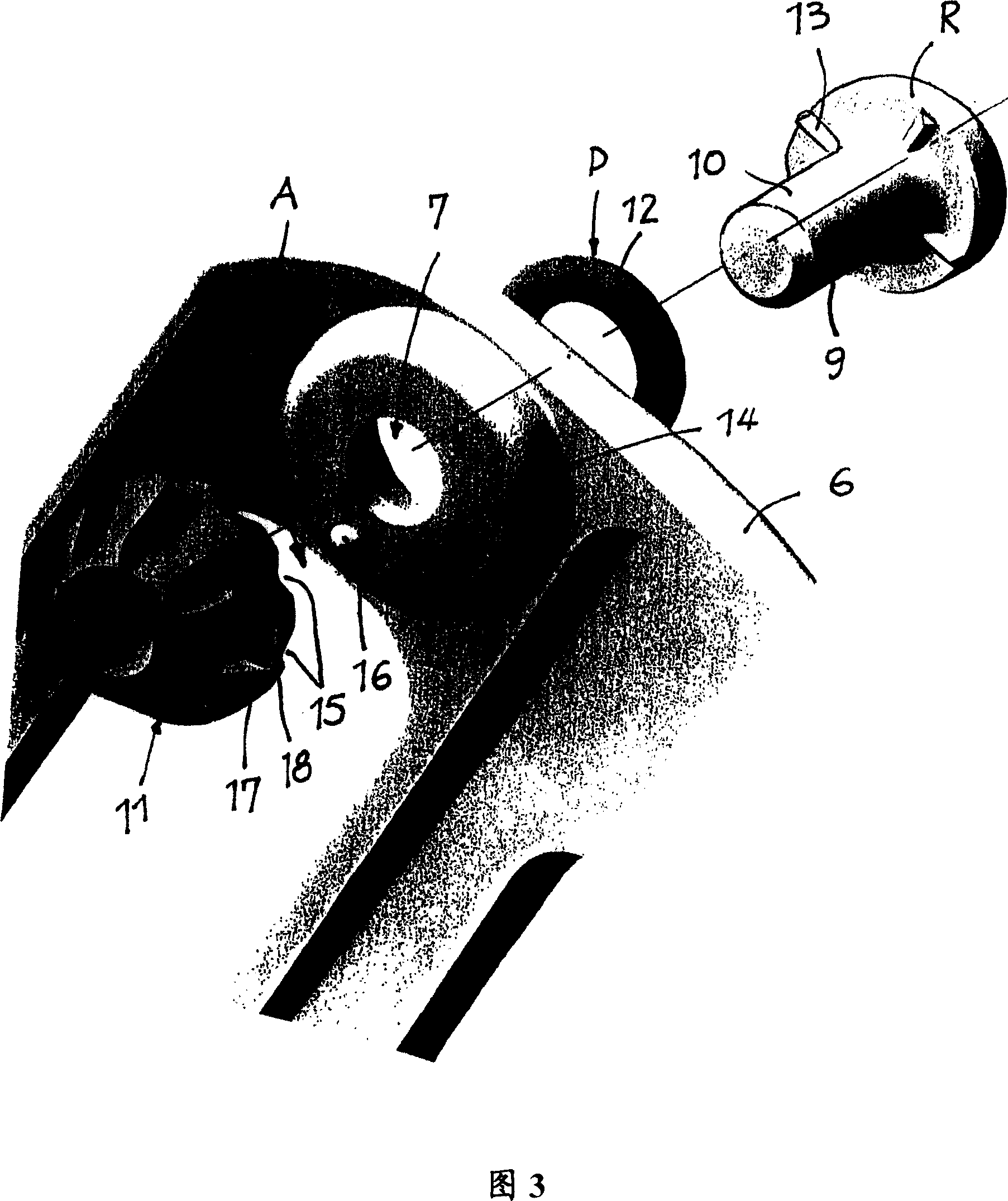
[0027] The brake housing 3 comprises a pin-shaped brak...


PUM


Abstract

A yarn feeder (F) comprising a storage body (2), at least one photoelectric reflective sensor (S), for the photoelectric reflective sensor (S), a reflector body (R) mounted in a storage body container (7) for For height adjustment between several different operating positions with respect to an adjacent storage surface (8), said reflector body (R) is arranged on bolts (9) passing through a spacer element (D), said spacer element (D) Arranged in the storage body container (7) and the countersunk element (K) is located on the lower surface (14) of the storage body container (7), characterized in that it includes at least one for all work of the reflector body (R) Preloaded and elastically compressible padding element (D) permanently retained in position in the storage body container (7).

Description

technical field [0001] The invention relates to a yarn feeder according to the preamble of claim 1 . Background technique [0002] Depending on the quality of the yarn processed in the yarn feeder and / or according to the yarn treatment process with paraffin, oil or other substances, the height position of the top surface of the reflector needs to be adjusted accordingly, so that the top surface or protrudes from the adjacent storage surface , or substantially flush with the adjacent storage surface, or set back relative to the storage surface. [0003] The yarn feeder in US-A-4,936,356 has a reflector body mounted in the reflector body container by a metal washer under the reflector body in the storage body container and a countersunk nut at the free end of the threaded bolt, thereby sinking The head nut engages the lower surface of the storage body receptacle and pulls the reflector body against the gasket. This adjustment defines a specific working position of the top su...

Claims


Application Information

Patent Timeline
IPC IPC(8): B65H51/22D03D47/36
CPCD03D47/367
Inventor 杰拉尔多·索尔顿
Owner IRO AB
Why Eureka
Try Eureka