Fire extinguishing system

A technology of fire extinguishing system and fire extinguishing medium, which is applied in fire rescue, fuel cell, life-saving equipment, etc., and can solve problems such as damage to fuel cell components, unsuitable electrical components, and insufficient function

Active Publication Date: 2007-04-11
WARTSILA FINLAND OY
View PDF0 Cites 11 Cited by
  • Summary
  • Abstract
  • Description
  • Claims
  • Application Information

AI Technical Summary

Problems solved by technology

In the event of a fire, the main CO in the engine room 2 Undesirable delays in the system and increased damage to fuel cell components
Additionally, the CO released by the engine room around the fuel cell components 2 role

Method used


Image

  • Fire extinguishing system
  • Fire extinguishing system

Examples


Embodiment Construction

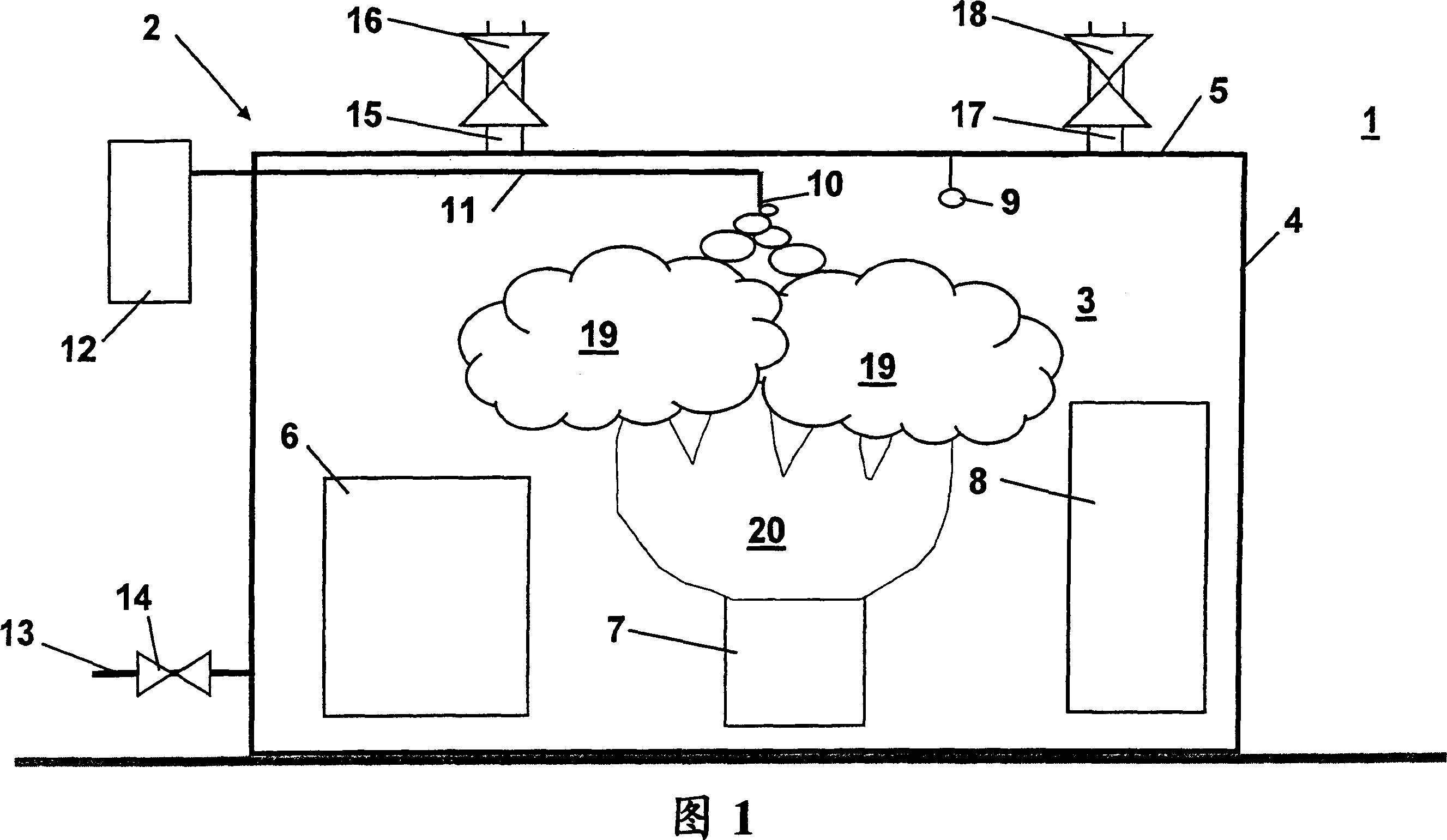
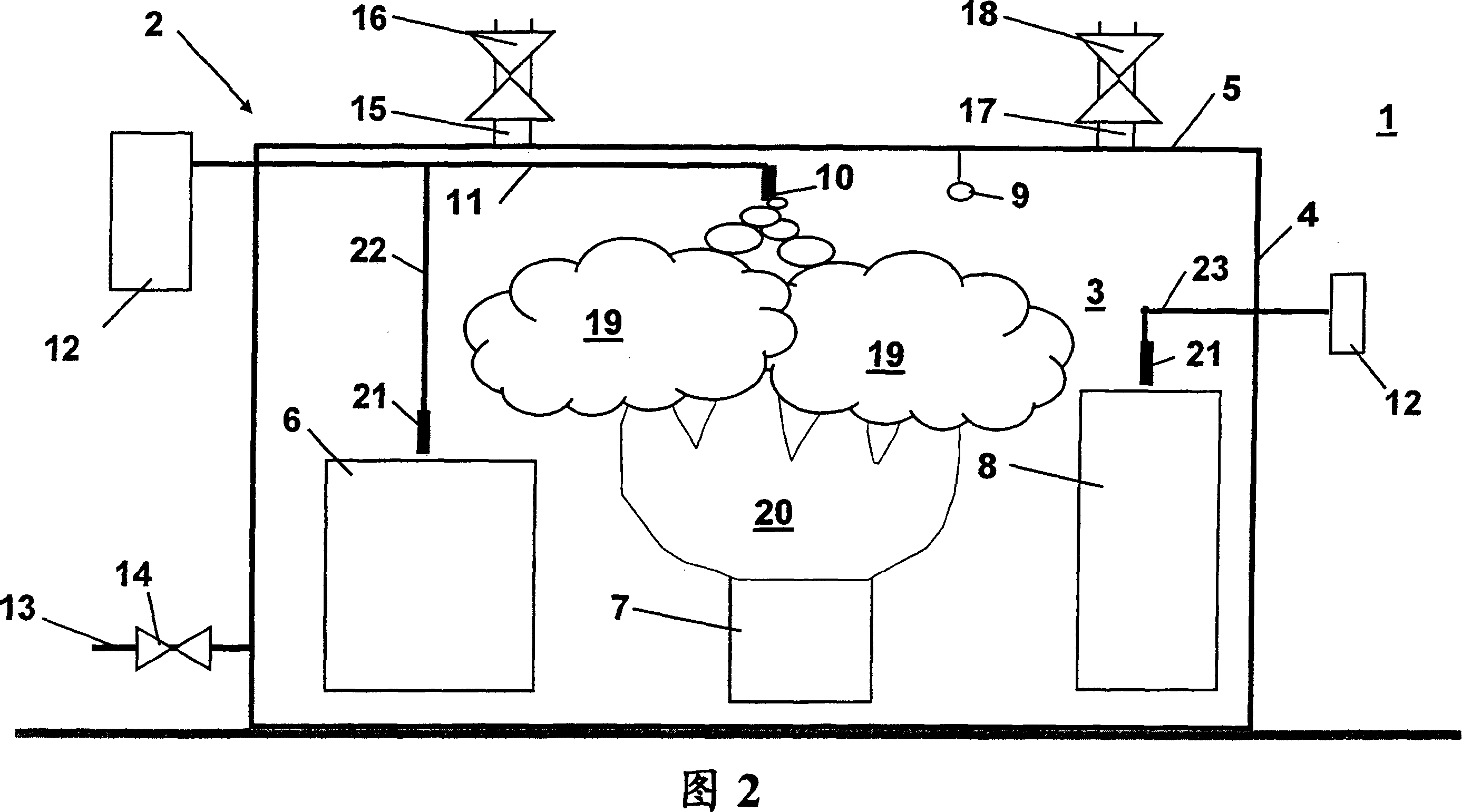
[0018] FIG. 1 shows a general view of a fuel cell assembly in the form of a fuel cell module 2 . The fuel cell module 2 is located in the engine room 1 of the marine vessel. In this embodiment, the fuel cell module 2 is enclosed in a container structure 3 provided with side walls 3 and a top wall 5 . The fuel cell module 2 includes a plurality of components. Figure 1 shows only some components generally as examples, such as fuel cell stack 6, auxiliary equipment 7 including fuel converters, heat exchangers, pumps, etc.; and power conditioner 8 including electrical converters and transformers.

[0019] The fuel cell module is provided with a flame detection sensor 9 inside the container. The flame detection sensor 9 preferably includes a smoke detector and a heat detector to ensure detection of a gas fire. Furthermore, the fuel cell module 2 includes internal nozzles 10 to release the extinguishing medium to the fuel cell module. The flame detection sensor 9 and the inner n...


PUM


Abstract

The invention relates to a fire extinguishing system for a marine vessel comprising an engine room (1) and a fuel cell arrangement. In order to improve the fire extinguishing system with respect to the fuel cell arrangement comprising at least one fuel cell module (2), the fuel cell module (2) is provided with at least one fire detection sensor (9) and at least one internal nozzle (10) for releasing a fire extinguishing medium into the fuel cell module.

Description

technical field [0001] The invention relates to a fire extinguishing system for a marine vessel comprising an engine room and a fuel cell assembly according to the preamble of claim 1 . Background technique [0002] Fire extinguishing systems are generally required in engine rooms or machine rooms of marine vessels or other marine structures, such as drilling platforms and liquefied natural gas stations. The fire suppression system is generally designed for the entire engine room CO 2 system. In addition, the so-called prime movers must be provided with a local fire extinguishing system. In practice, this means that the water mist spraying device is placed above the engine or other machinery and equipment. [0003] CO 2 The system is effective, but cannot be used until the entire engine room is emptied, i.e. all personnel are evacuated. This usually means delayed release of CO 2 , which increases the destructiveness of the fire. To ameliorate this situation requires t...

Claims


Application Information

Patent Timeline
IPC IPC(8): A62C3/10A62C37/36A62CB63J99/00
CPCY02E60/50H01M2200/00H01M8/2475A62C3/16A62C3/10Y02E60/10A62C37/04
Inventor O·利万德
Owner WARTSILA FINLAND OY
Why Eureka
Try Eureka