Vehicle rear combined lamp

A rear combination lamp and vehicle technology, which is applied to road vehicles, vehicle parts, motor vehicles, etc., can solve the problem of low visibility and achieve the effects of improved visibility, improved visibility, and novel appearance

Inactive Publication Date: 2007-04-11
HONDA MOTOR CO LTD
View PDF1 Cites 10 Cited by
  • Summary
  • Abstract
  • Description
  • Claims
  • Application Information

AI Technical Summary

Problems solved by technology

[0005] The above-mentioned LED24 and LED211 have strong directivity, so although the visibility when viewed from the rear of the vehicle is high, the visibility when viewed from the side of the vehicle is not high.

Method used


Image

  • Vehicle rear combined lamp
  • Vehicle rear combined lamp
  • Vehicle rear combined lamp

Examples


Embodiment Construction

[0048] Hereinafter, preferred modes for implementing the present invention will be described with reference to the drawings. In addition, the drawings should be viewed in the direction of the labels.

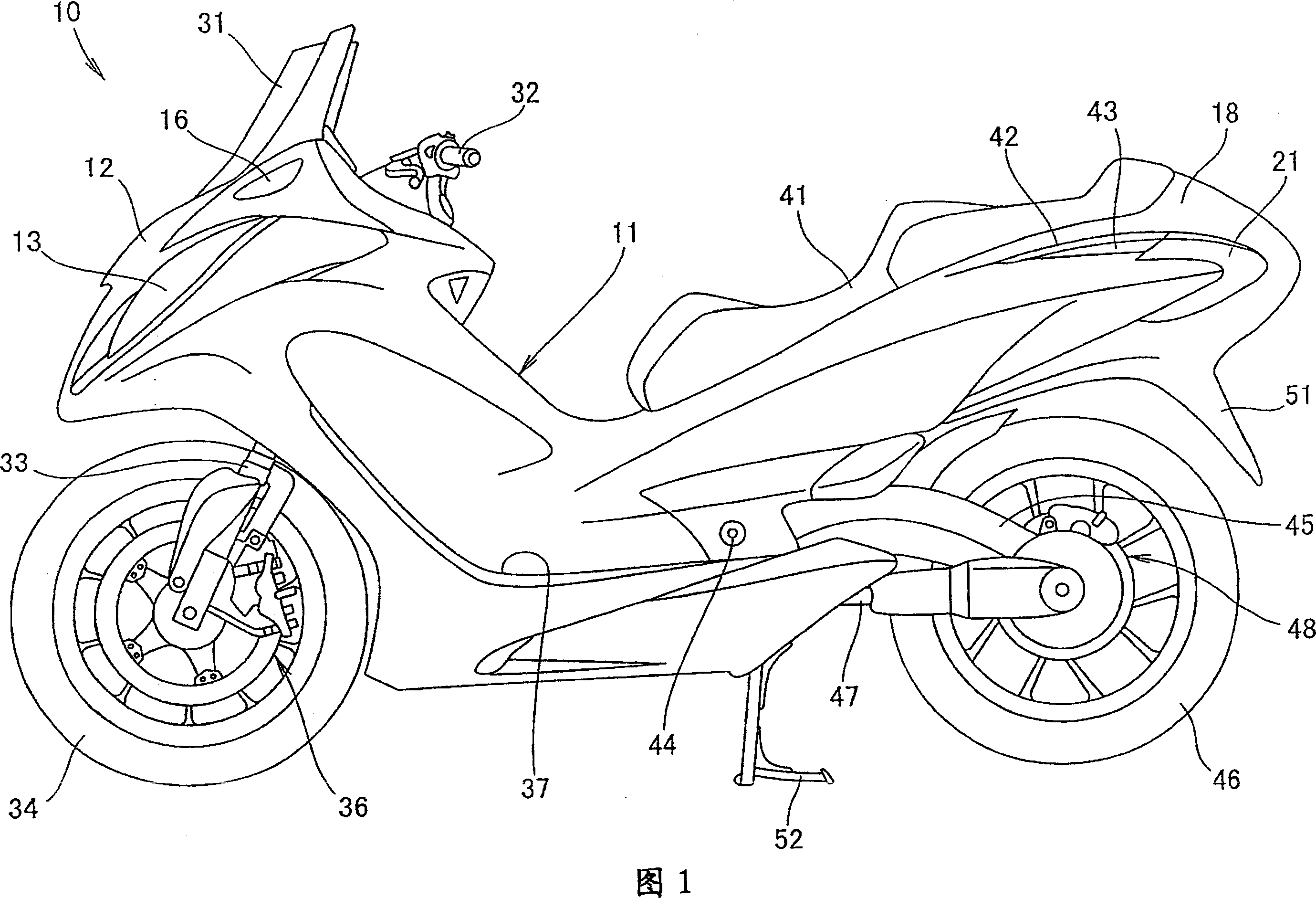
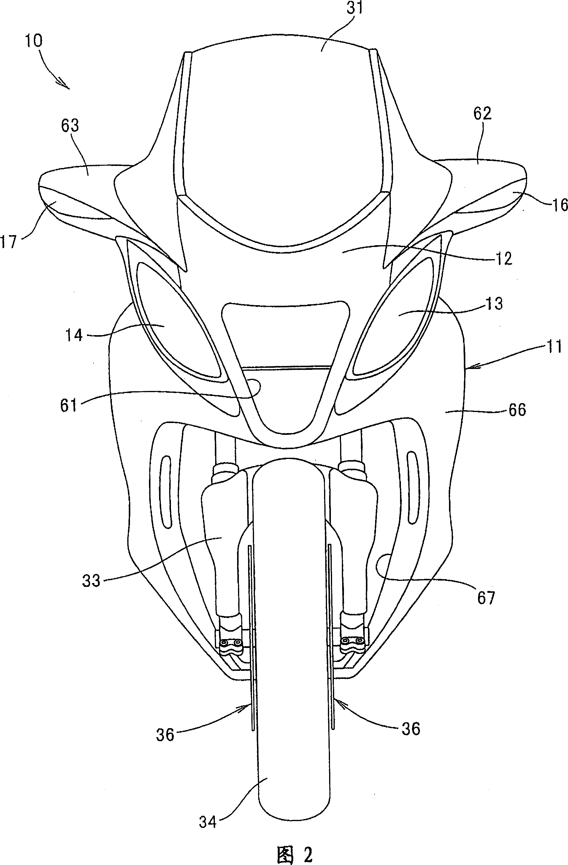
[0049] 1 is a side view of a vehicle with a rear combination lamp related to the present invention. The vehicle 10 is a scooter type motorcycle with a structure as follows: a pair of left and right head lamps (head lamps) 13, 14 ( Reference numeral 13 showing only the front side and front turn signals 16, 17 (reference number 16 showing only the front side) as a pair of left and right blinkers are disposed on a front cover (front cover) constituting the front portion of the vehicle body cover 11. 12, a pair of left and right rear combination lamps 21, 22 (only the reference numeral 21 on the front side) are arranged on the rear cover member 18 constituting the rear portion of the vehicle body cover 11. In the lamps 16, 17, and the rear combination lamps 21, 22, LEDs (Light Emit...


PUM


Abstract

A vehicle rear combined lamp can enhance visibility of a rear combination lamp from the rear side of a vehicle and the side of the vehicle. The vehicle provided with this rear combination lamp using LEDs (131) as light sources is provided with a light guide body (101) projecting to the rear side of the vehicle from the front part of a lamp housing (111) for guiding the light of the LEDs (131) to the rear side of the vehicle. The LEDs (131) are respectively arranged in the front part of the light guide body (101), and a peripheral edge (101a) as a light emission surface oriented to the rear side of the vehicle and the side of the vehicle is formed in the rear part of the light guide body (101).

Description

technical field [0001] The present invention relates to rear combination lamps for vehicles. Background technique [0002] As a conventional rear combination lamp of a vehicle, a structure using an LED (Light Emitting Diode) as a light source is known (for example, refer to Patent Document 1). [0003] Patent Document 1: Japanese Patent Laid-Open No. 2004-203370 [0004] As shown in FIG. 1 of Patent Document 1, the tail lamp 18 is composed of an upper lighting portion 20 and a lower lighting portion 21 . In the upper lighting part 20, LED24 is provided as a position lamp; in the lower lighting part 21, a plurality of LED211 are provided as brake lights. [0005] Since the above-mentioned LED 24 and LED 211 have strong directivity, the visibility when viewed from the vehicle rear is high, but the visibility when viewed from the side of the vehicle is not high. [0006] An object of the present invention is to improve the visibility of a rear combination lamp from the rear ...

Claims


Application Information

Patent Timeline
Patent Type & Authority Applications(China)
IPC IPC(8): F21S8/10F21V8/00B60Q1/30F21W101/02F21W107/10
Inventor 向后智大桥速人
Owner HONDA MOTOR CO LTD
Why Eureka
Try Eureka