Composite twistless compound pendulus rod

A composite and composite structure technology, applied in the field of compound pendulum, can solve problems such as large measurement errors, and achieve the effects of reducing manufacturing costs, reducing measurement errors, and relaxing the combination of precision

Inactive Publication Date: 2007-04-11
SICHUAN UNIV
View PDF0 Cites 14 Cited by
  • Summary
  • Abstract
  • Description
  • Claims
  • Application Information

AI Technical Summary

Problems solved by technology

The important thing is that this contact point is not at the center of the hole top of the swing rod, but at a certain end of the hole top. In this case, the

Method used


Image

  • Composite twistless compound pendulus rod
  • Composite twistless compound pendulus rod

Examples


Embodiment Construction

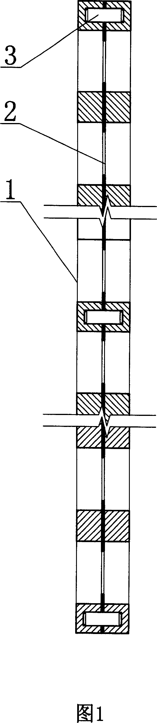
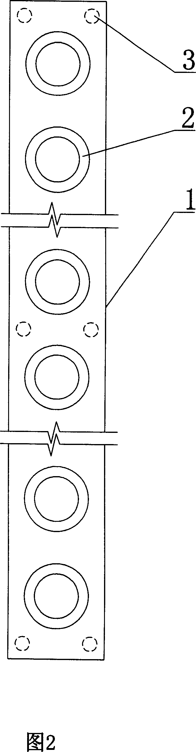
[0011] The pendulum is made into a rectangular shape with a length of 60cm and a width of 3cm. The distance between the centers of two adjacent holes is 2.2cm. The number of holes is 26. The material of the middle layer is stainless steel, and its hole diameter is 9mm. The thickness of the middle layer is 0.2mm, both outer layers are aluminum plates with a thickness of 2.4mm, and the hole diameter is 1.2cm. After compounding, the center of each layer of holes is on the longitudinal centerline of the swing rod, and each corresponding hole is concentric. Three layers The center is compounded by six pins with the longitudinal and transverse centerlines of the swing rod as the symmetry axis. There are two pins at each end of the swing rod, and the remaining two pins are in the middle.


PUM


Abstract

The invention relates to a compound swing bar without twist. It takes the structure of three-lay composite sandwich, and the aperture of middle layer is less than that of outer, which thickness is 0.2~0.3 mm in control. So that the line contact between hole on the rocker and top edge of the prism is changed into the point contact on the midpoint of hole to make the rocker hang in a vertical state, eliminate twisting, save time and reduce measure error and cost.

Description

1. Technical field [0001] The invention relates to a compound pendulum in a physical experiment instrument, in particular to a compound pendulum pendulum bar capable of eliminating twisting. 2. Background technology [0002] Presently known compound pendulum is made of two parts: the one, fork, the 2nd, support, and wherein the profile of fork is a rectangular metal plate, and dozens of circular through holes are distributed along the longitudinal center line on the plate. In the experiment, the hole of the swing rod is set on a triangular prism arranged horizontally above the bracket, and the top of the hole of the swing rod is combined with the edge above the triangular prism. When the lower end of the swing rod is pulled away from the equilibrium position and released, the swing rod begins to swing. According to the experimental principle, this swing must be a smooth swing in a vertical plane, so that the error of the acceleration of gravity measured by this will tend to...

Claims


Application Information

Patent Timeline
IPC IPC(8): G09B23/06
Inventor 梁德富张明宪
Owner SICHUAN UNIV
Why Eureka
Try Eureka