
Combined twistless compound pendulum

A combined and bending technology, applied in the field of compound pendulum, can solve problems such as large measurement errors

Inactive Publication Date: 2007-04-11
SICHUAN UNIV
View PDF0 Cites 17 Cited by
  • Summary
  • Abstract
  • Description
  • Claims
  • Application Information

AI Technical Summary

Problems solved by technology

Moreover, the contact point with each other is not at the center point of the hole top of the swing rod, but at a certain end of the hole top. In this case, the swing rod cannot be in a vertical state, so once it swings, it will inevitably appear. Obvious twisting, which eventually causes large measurement errors

Method used


Image

  • Combined twistless compound pendulum
  • Combined twistless compound pendulum

Examples


Embodiment Construction

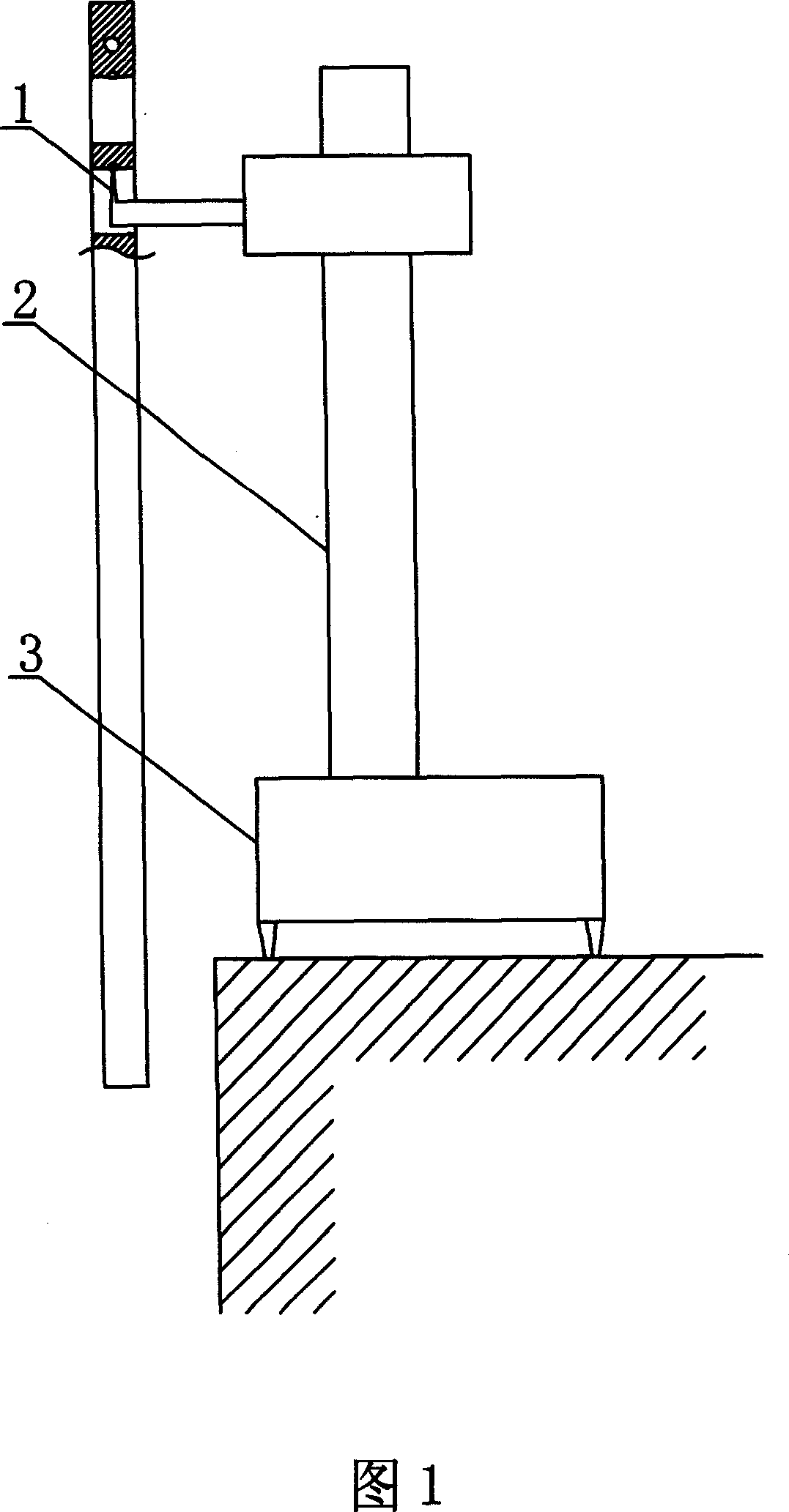
[0012] The complex pendulum pendulum bar (4) that has finished drilling operation is cut into two halves along the longitudinal centerline with a wire cutting machine tool, and then on each concave semi-cylindrical surface of the two halves respectively by the suspension end. Open a gap at the midpoint of one side edge, the width of the gap is 1.5mm, and the depth is 1mm, then use pins (5) to combine the sections of the two halves into a whole, and fix the bent support cone (1) on the Above the compound pendulum bracket (2), the support part of the bent support cone (1) is conical, the diameter of the bottom surface of the cone is 3 mm, and the length is 8 mm. When the swing rod (4) is suspended on the bent support cone (1) Finally, the conical apex of the bent support cone is in the depression at the top of the fork (4) hole.


PUM

PropertyMeasurementUnit
Diameteraaaaaaaaaa
Lengthaaaaaaaaaa

Abstract

The invention relates to a compound swing bar without twist. The rocker is made to be one left and one right structure, of which, the midpoint of one edge on two sides of semi-cylindrical concave is opened and combined with pin. The prism on the top of support is made to be the bended supporting awl to form a point contact between the hollow of the top of midpoint on rocker and the peak of bended supporting awl to make the rocker hang in a vertical state, thereby eliminating twisting, saving time, reducing the measure error and cost.

Description

1. Technical field [0001] The invention relates to a compound pendulum in a physical experiment instrument, in particular to a compound pendulum capable of eliminating twisting. 2. Background technology [0002] Presently known compound pendulum is made of two parts: the one, fork, the 2nd, support, and wherein the profile of fork is a rectangular metal plate, and dozens of circular through holes are distributed along the longitudinal center line on the plate. In the experiment, the hole of the swing rod is set on a triangular prism arranged horizontally above the bracket, and the top of the hole of the swing rod is combined with the edge above the triangular prism. When the lower end of the swing rod is pulled away from the equilibrium position and released, the swing rod begins to swing. According to the experimental principle, this swing must be a smooth swing in a vertical plane, so that the error of the acceleration of gravity measured by this will tend to be the small...

Claims


Application Information

Patent Timeline
IPC IPC(8): G09B23/06
Inventor 梁德富张明宪
Owner SICHUAN UNIV
Learn More