Outdoor high voltage double power source vacuum breaker

A vacuum circuit breaker and dual power supply technology, applied in high voltage air circuit breakers, high voltage/high current switches, circuits, etc., can solve the problems of no isolation fracture, large footprint, and parallel operation of two power sources.

Inactive Publication Date: 2007-04-11
BAOGUANG GROUP
View PDF8 Cites 42 Cited by
  • Summary
  • Abstract
  • Description
  • Claims
  • Application Information

AI Technical Summary

Problems solved by technology

But there are also obvious disadvantages: (1) large investment
The cost of the switchgear is very high, and to achieve dual power supply, at least two or more high-voltage switchgears are required, and the cost is obviously higher than other solutions
(2) It covers a large area, and it is necessary to build a special power distribution room and be equipped with related supporting facilities, which requires a large investment in infrastructure
In the mining area, there is a problem with the construction of the power distribution room
(3) Poor environmental adaptability
The general operating temperature range of high-voltage switchgear is -5°C ~ +40°C. In severe cold areas, heating measures are required to increase maintenance costs.
(4) The interlocking and operating procedures are complex, and it is easy to fail to achieve the expected function due to failure to operate according to the operating procedures
(5) If there is no electric isolating switch to realize the isolation of the two power sources, as long as the insulation failure of the breaker breaker (such as air leakage in the vacuum interrupter, etc.) occurs, it is easy to cause the parallel operation of the two power sources or the reverse power transmission accident
However, because it is based on a load switch, it cannot achieve short-circuit protection, so it must be equipped with a fuse to achieve short-circuit protection
And there is no obvious isolation fracture, and an isolation switch must be configured separately to realize line inspection and maintenance

Method used


Image

  • Outdoor high voltage double power source vacuum breaker
  • Outdoor high voltage double power source vacuum breaker
  • Outdoor high voltage double power source vacuum breaker

Examples


Embodiment Construction

[0011] The present invention will be further described below in conjunction with the embodiments and accompanying drawings.

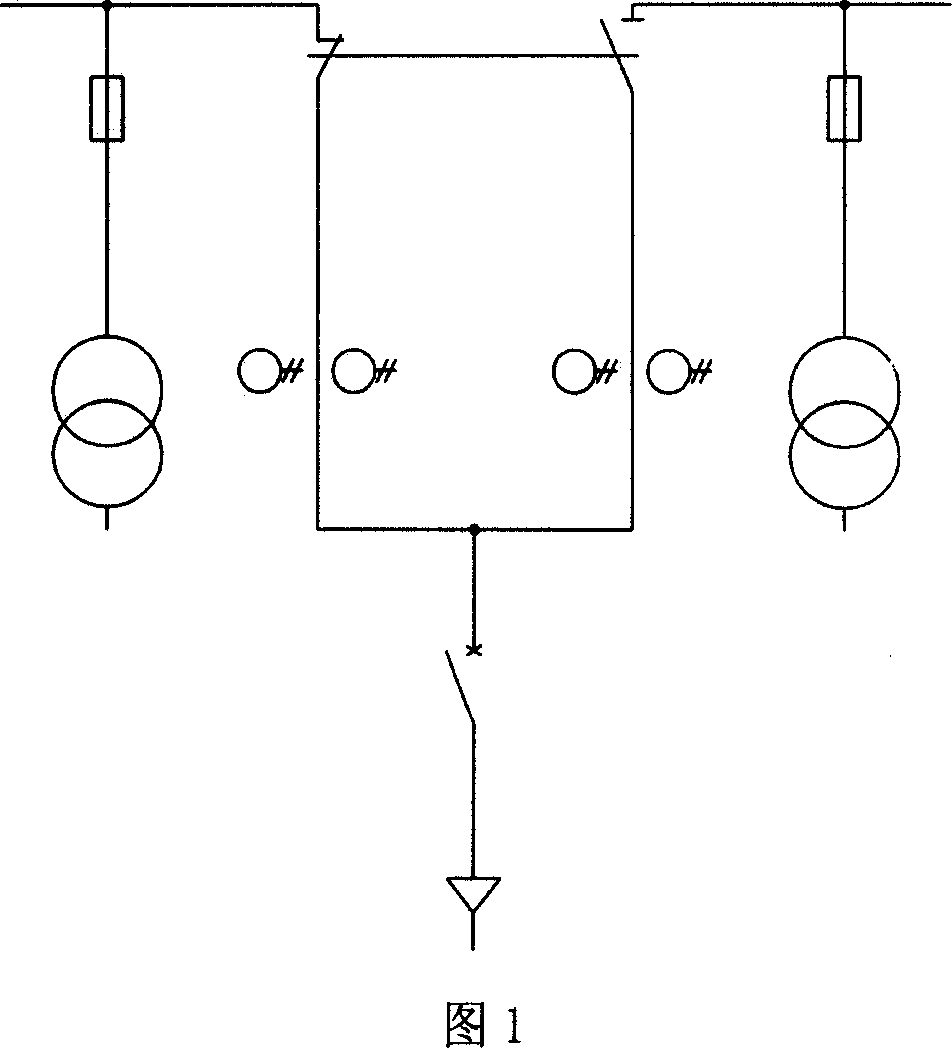
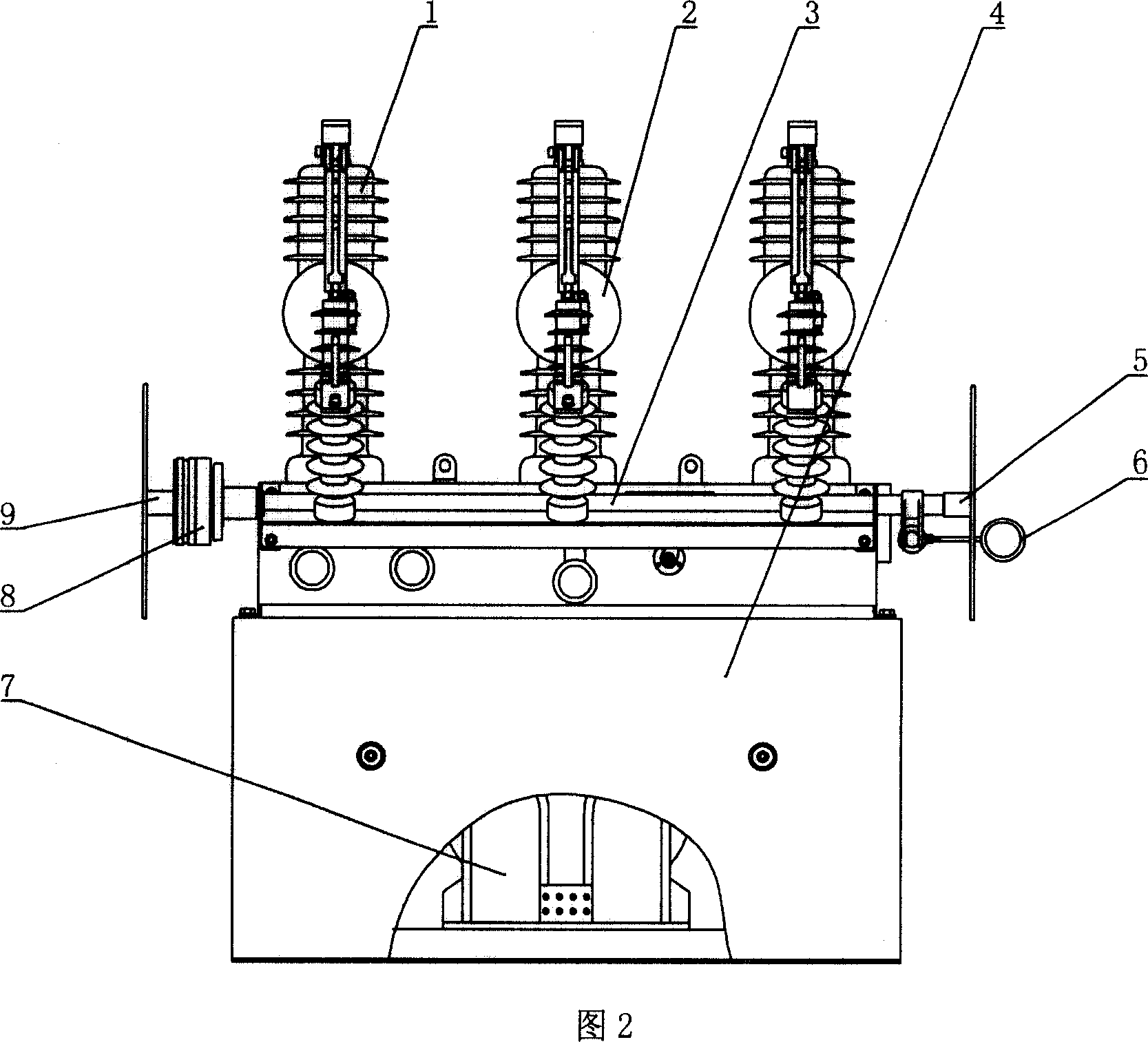
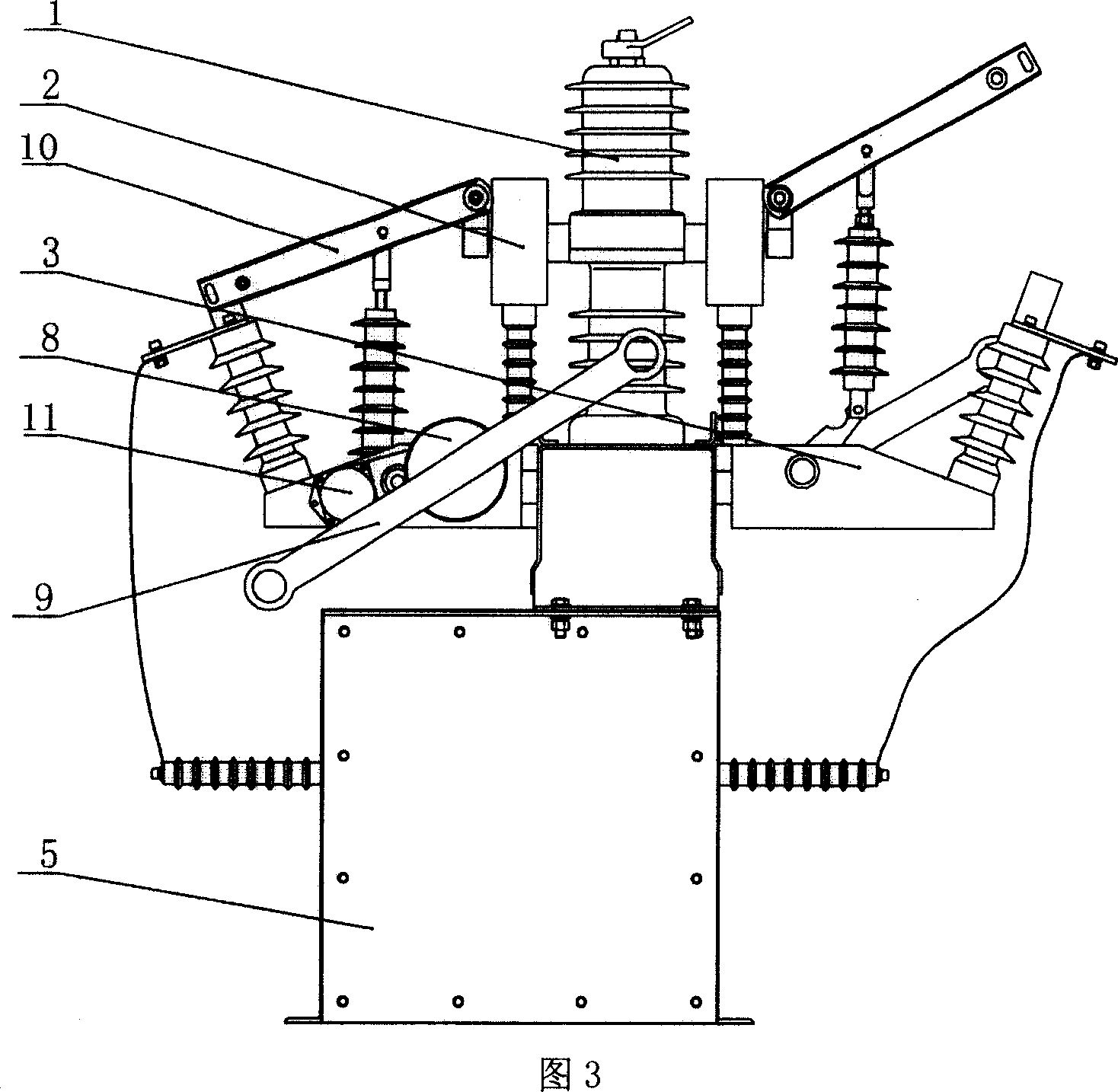
[0012] Referring to Figures 2 to 4, an outdoor high-voltage dual-power vacuum circuit breaker includes a three-phase outdoor high-voltage vacuum circuit breaker 1, a voltage transformer 7, a current transformer 2, an isolation switch 3, 10, an automatic controller, and a waterproof A voltage transformer 7 is installed in the base 4, a three-phase outdoor high-voltage vacuum circuit breaker 1 is installed on the base 4, and a current transformer 2 is installed on both sides of the lower outlet of the three-phase outdoor high-voltage vacuum circuit breaker 1, and the current transformer 2 is connected to the disconnector 3, 10 connection, the two sides of the three-phase outdoor high-voltage vacuum circuit breaker 1 are also equipped with mechanical interlocking devices 12, 14 with the three-phase outdoor high-voltage vacuum circuit breaker 1 and the isola...


PUM


Abstract

This invention relates to an outdoor high voltage double supply vacuum breaker including a three-phase outdoor high voltage vacuum breaker, voltage mutual inductors, current mutual-inductors, isolation switches and an automatic controller, in which, the voltage mutual-inductor is set in a water-proof base and the three-phase outdoor high voltage vacuum breaker is set on the base, current mutual-inductors are installed on both sides of the outlets under the breaker and connected with the isolation switch, mechanical interlockers for the breaker and the isolation switch are mounted at both sides of the breaker, the shafts of the two sides of the isolation switches are connected by a linkage rod, a release device is set on the linkage rod, an overhaul operation handle is set on a shaft end of an isolation switch at one side, and an electromotive clutch is set on the other side with a manual operation handle is set on its end, the clutch device is meshed with the drive motor.

Description

1. Technical field [0001] The invention relates to an outdoor high-voltage double-power vacuum circuit breaker used for a high-voltage double-power supply line. 2. Background technology [0002] Now, many power users who have high requirements for power supply safety and reliability, in order to ensure the continuity of power supply, use two 10kV high-voltage power supplies (high-voltage dual power supplies) for power supply, which can greatly improve the reliability and safety of power supply To ensure equipment and personal safety. However, if two high-voltage power supplies are used for power supply, there is a problem of how to switch and protect the two power supplies. That is, after one power supply fails, how to quickly and safely switch to another power supply. At present, there are mainly the following schemes: (1) Use multiple indoor high-voltage switch cabinets to realize switching and protection of high-voltage dual power supplies. This is the most widely used...

Claims


Application Information

Patent Timeline
Patent Type & Authority Applications(China)
IPC IPC(8): H01H33/66H01H33/666H01H33/52H01H33/36H01H33/02H02H3/10H02J9/04
Inventor 张兴前张林关禄海罗敬泽刘峰苏小利
Owner BAOGUANG GROUP
Why Eureka
Try Eureka