Emergency rescue water cannon device

An emergency rescue and water cannon technology, which is applied in fire rescue and other fields, can solve the problems of high danger, secondary disasters, poor safety, etc., and achieve the effect of simple overall structure, low cost and small size

Pending Publication Date: 2019-12-27
JIEDA FIRE PROTECTION VEHICLE EQUIP CO LTD SUZHOU CITY +1
View PDF5 Cites 4 Cited by
  • Summary
  • Abstract
  • Description
  • Claims
  • Application Information

AI Technical Summary

Problems solved by technology

As far as the aforementioned barrier lake is concerned, it is formed due to landslides, seasonal snowmelt in snow mountains, and mud-rock flows caused by persistent and heavy precipitation that block the river and store a large amount of water. If the drainage and flood discharge of the barrier lake is not timely and the measures are improper , will cause immeasurable losses
At present, traditional blasting methods, manual excavation of flood outlets, installation of diversion pipes, etc. are still commonly used for drainage and flood discharge of barrier lakes. On the one hand, this method is dangerous and the cost of flood discharge is high, and on the other hand, it is not safe. And there is a risk of causing secondary disasters; as far as the aforementioned fire extinguishing is concerned, in many fire scenes, especially hazardous chemical fire scenes, it is difficult or even not allowed for fire-fighting vehicles and firefighters to get too close, so the speed of fire-fighting and fire-fighting adverse effects

Method used


Image

  • Emergency rescue water cannon device
  • Emergency rescue water cannon device
  • Emergency rescue water cannon device

Examples


Embodiment Construction

[0020] In order to understand the technical essence and beneficial effects of the present invention more clearly, the applicant will describe in detail the following examples, but the descriptions of the examples are not intended to limit the solutions of the present invention. Equivalent transformations that are only formal but not substantive should be regarded as the scope of the technical solution of the present invention.

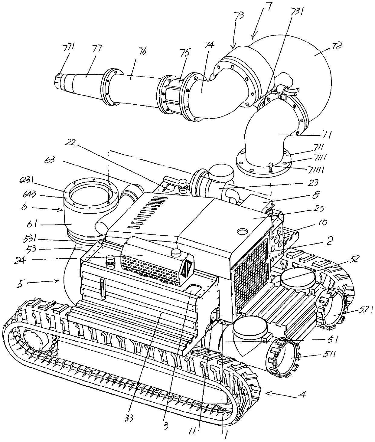
[0021] In the following descriptions, all concepts related to directionality or orientation of up, down, left, right, front and back are based on figure 1 The current location status is a reference, so it cannot be understood as a special limitation on the technical solution provided by the present invention.

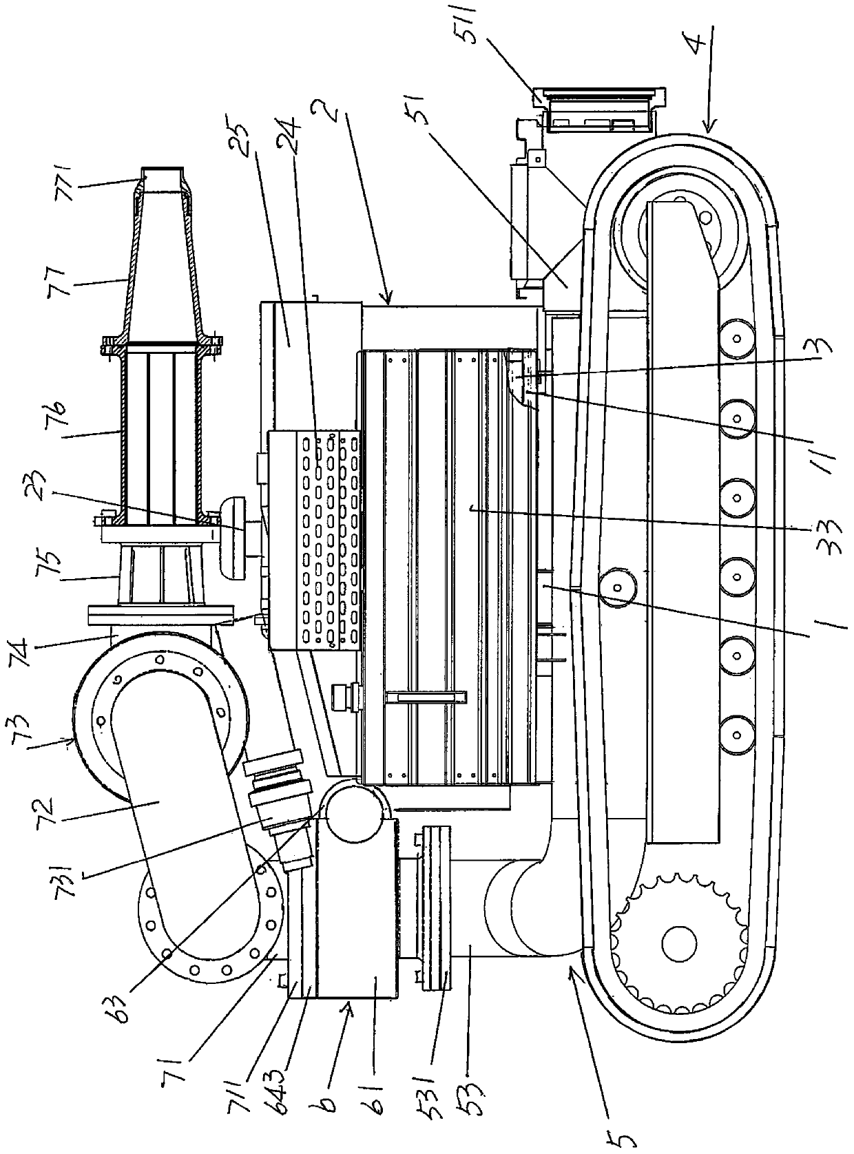
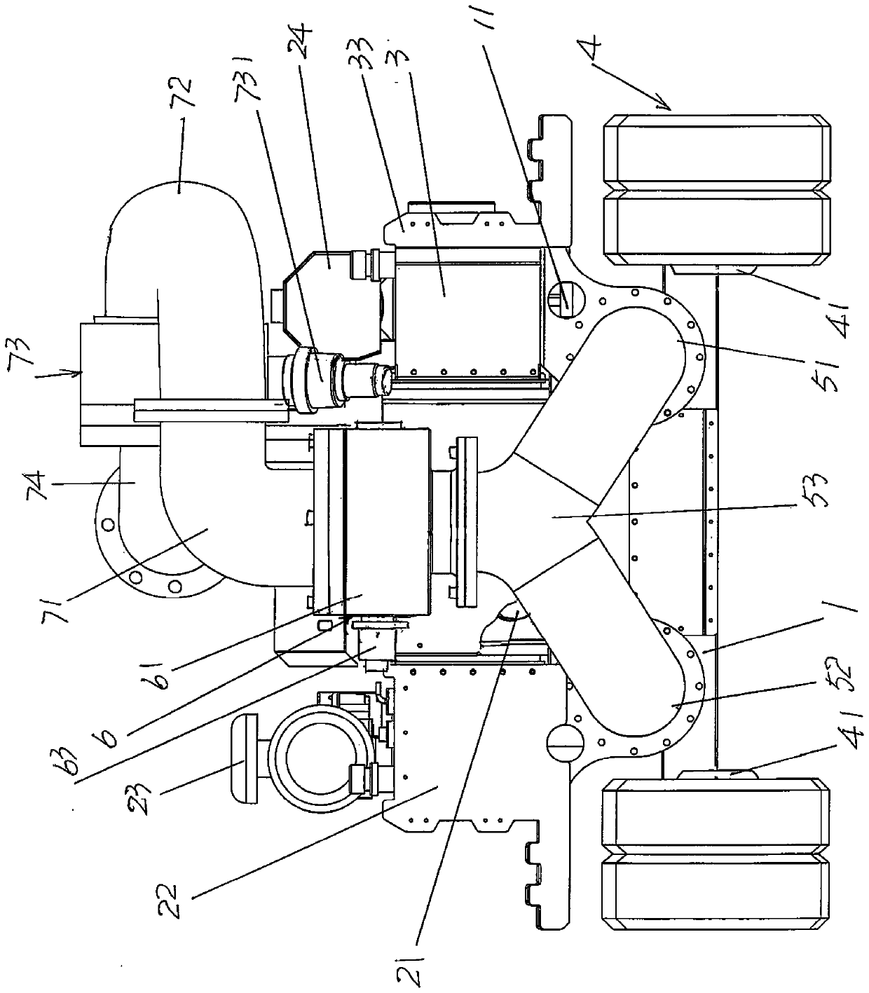
[0022] See Figure 1 to Figure 4, shows a frame 1, and this frame 1 has a frame carrying platform 11; Shows a diesel engine 2, and this diesel engine 2 is arranged on the aforementioned frame platform 11, driven by the diesel engine 2 and its o...


PUM


Abstract

The invention discloses an emergency rescue water cannon device, and belongs to the technical field of emergency rescue facilities. The device comprises a rack, a diesel engine, a high-pressure oil tank, a crawler travelling mechanism, a water diversion mechanism, a water cannon base rotary mechanism, a water cannon assembly and a remote control signal receiver, wherein the rack is provided with arack bearing platform; the diesel engine is arranged on the rack bearing platform; the high-pressure oil tank is arranged on the rack bearing platform; the crawler travelling mechanism and the waterdiversion mechanism are arranged on the rack, and the crawler travelling mechanism drives the rack and the rack bearing platform to travel; the water cannon base rotary mechanism is connected with thewater diversion mechanism, the water cannon assembly is rotationally connected with the water cannon base rotary mechanism, the crawler travelling mechanism, the water cannon base rotary mechanism and the water cannon assembly are connected with a pressure oil distribution control valve oil way; and the remote control signal receiver is arranged on the rack bearing platform. The automatic travelling effect of a robot is embodied so as to meet the requirement that the manual operation of rescue personnel is not needed; the requirement of a barrier lake for effective flood discharge through damimpacting and the requirement for near fire fighting of a hazardous chemical product fire scene which does not allow a fire fighting vehicle and fire fighting personnel to get close to can be met; and the structure is simple, the size is small, and the requirements of being flexible, economic and cheap can be met.

Description

technical field [0001] The invention belongs to the technical field of emergency rescue facilities, and in particular relates to an emergency rescue water cannon device. Background technique [0002] The emergency rescue mentioned above mainly includes the emergency treatment of the barrier lake and fire fighting, but it is not limited by the application occasions listed above. As far as the aforementioned barrier lake is concerned, it is formed due to landslides, seasonal snowmelt in snow mountains, and mud-rock flows caused by persistent and heavy precipitation that block the river and store a large amount of water. If the drainage and flood discharge of the barrier lake is not timely and the measures are improper , will cause immeasurable losses. At present, traditional blasting methods, manual excavation of flood outlets, installation of diversion pipes, etc. are still commonly used for drainage and flood discharge of barrier lakes. On the one hand, this method is dange...

Claims


Application Information

Patent Timeline
Patent Type & Authority Applications(China)
IPC IPC(8): A62C27/00A62C31/00A62C31/28A62C37/00
CPCA62C27/00A62C31/00A62C31/28A62C37/00
Inventor 张建明邓立刚
Owner JIEDA FIRE PROTECTION VEHICLE EQUIP CO LTD SUZHOU CITY
Why Eureka
Try Eureka