Actuator for operation of gearless driving machine of elevator

A transmission gear and drive equipment technology, applied in the field of wheel drive equipment, can solve the problems of unsafe, expensive, and complicated operations, and achieve the effect of easy installation

Inactive Publication Date: 2006-03-15
INVENTIO AG
View PDF1 Cites 0 Cited by
  • Summary
  • Abstract
  • Description
  • Claims
  • Application Information

AI Technical Summary

Problems solved by technology

This device is expensive, complicated, and less safe to operate

Method used


Image

  • Actuator for operation of gearless driving machine of elevator
  • Actuator for operation of gearless driving machine of elevator
  • Actuator for operation of gearless driving machine of elevator

Examples


Embodiment Construction

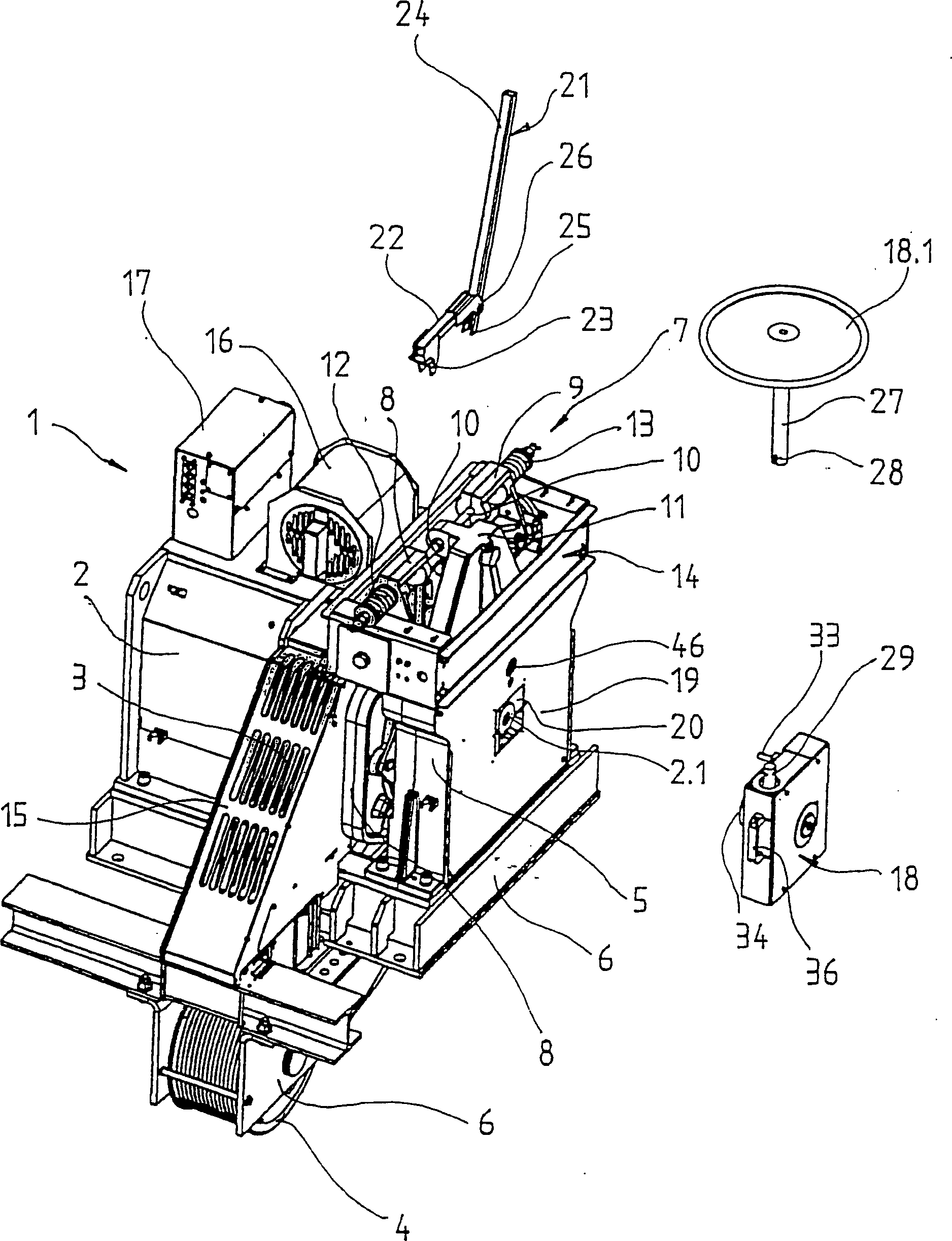
[0014] figure 1 A gearless drive unit 1 is shown with an electric motor 2 consisting of a stator and a rotor for driving a drive wheel 3 . Cables not shown in the figure go around the driving wheel 3 and the reversing roller 4, said cables suspend an elevator car not shown in the figure and a counterweight not shown in the figure and drive the latter two. The driving wheel 3 is fixed on the motor shaft 2.1, one end of the motor shaft is pivotally connected to the bearing cap and the other end is pivotally connected to the bearing seat 5. Motor 2, bearing cover, bearing seat 5 and reversing roller 4 are fixed on the machine bracket 6.

[0015] The drive unit comprises a brake device 7 with a first brake lever 8 and a second brake lever 9 on which each a brake shoe is arranged. The lower ends of the brake levers 8 , 9 are pivotally connected to the bearing housing 5 and their upper ends are guided by a rod 10 . The middle of the rod 10 is set on a bracket 11 connected with th...


PUM


Abstract

The invention relates to a gearless driving machine (1) with a motor (2) that drives a drive sheave (3). Ropes that are not shown in the drawing are guided via the drive sheave (3) and a deflecting roller (4) and carry an elevator car, not shown in the drawing, and a counterweight, also not shown in the drawing. The drive sheave (3) is supported by a motor shaft (2.1) that is received on the one end by an end shield, not shown in the drawing, and on the other end by a bearing block (5). The motor (2), end shield, bearing block (5) and deflecting roller (4) are mounted on a machine console (6). For an emergency operation of the elevator, a manual drive (18) is provided that can be coupled with the motor shaft (2.1) without using tools. When the elevator is operated manually, a brake lifting lever (21) and the handwheel (18.1) are actuated until the elevator car reaches the next stop.

Description

technical field [0001] The present invention relates to a gearless driving device for an elevator. The driving device consists of a motor, a drive wheel fixed by the motor shaft, wherein the cable surrounds the drive wheel to carry and move the elevator car and counterweight, and a The braking device arranged on the bearing seat for braking the motor is composed of a control device for emergency operation, and the motor is manually operated by the control device. Background technique [0002] EP 0 706 968 A2 discloses a drive unit for an elevator. The drive unit has a continuous shaft which forms both the motor shaft and the transmission shaft. At one end of the shaft there is a transmission gear with a driving pulley for the elevator rope. Mount a handwheel on the free end of the shaft on the motor side for emergency operation of the drive unit. The rod holding the brake shoe is hinged on the base plate. A cylinder is used to press the brake shoe against the outer circl...

Claims


Application Information

Patent Timeline
Patent Type & Authority Patents(China)
IPC IPC(8): B66B5/02
CPCB66B5/027
Inventor 安德策伊·肖林斯基
Owner INVENTIO AG
Why Eureka
Try Eureka