
Eureka
For R&D, Eureka makes reading and utilizing patents & technical documents easy.
Eureka AIR
Designed for self-driven R&D workflows. Generate viable solutions, solve complex R&D challenges, empower your innovation with AI.

Eureka Materials
Designed for material experts only. Revolutionize your material R&D, from search, analyze, to developing new materials.

TechResearch
Generate reliable direction feasibility study reports for your R&D in just a few steps.

TechSeek
Discover and master advanced knowledge NOW. Basics, ideas, possibilities, all at once.

TechMind
As an expert in R&D Theories, TechMind can generates customized viable solutions instantly.

TechRisk
Analyze your overall solution with one click, know your potential R&D risks in advance.

TechMonitor
Get weekly tech updates, stay abreast of the latest tech innovations and key insights.
Electrical current measurements at head-disk interface
A current measuring device and current technology, applied in the protection measures of the magnetic head, aligning the magnetic tracks on the magnetic disk, recording information on the magnetic disk, etc., can solve the problems of interference measurement accuracy and so on
- Summary
- Abstract
- Description
- Claims
- Application Information
AI Technical Summary
Problems solved by technology
Method used
Image

Examples
Embodiment Construction
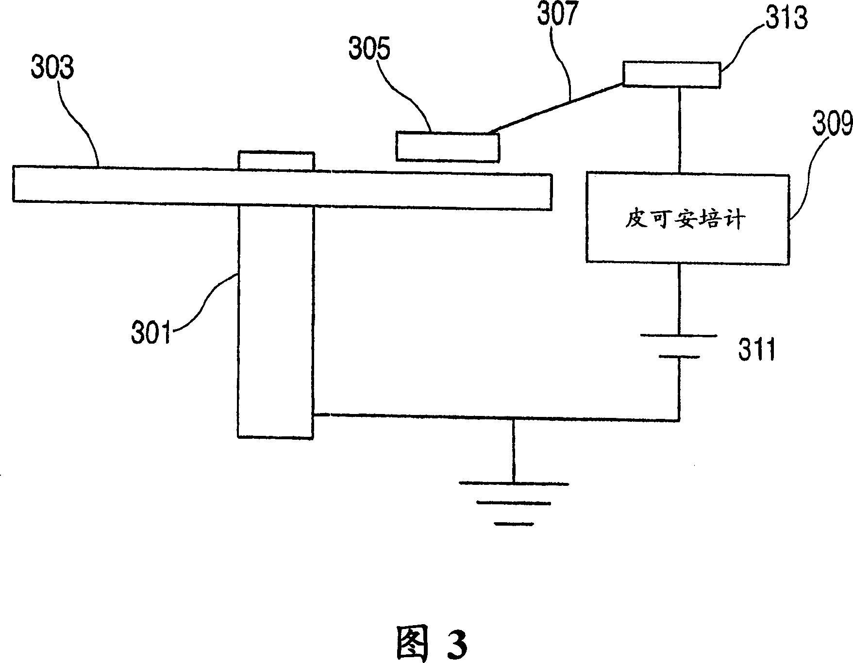
[0025]Referring to Figure 3, an apparatus for measuring current at the head-disk interface is shown. Like a conventional disk drive, a magnetic recording medium (such as a magnetic recording disk 303 ) rotating around a rotating shaft 301 is provided. In this example, the disk 303 is clamped to the shaft 301 and electrically grounded. A head, such as magnetic recording head 305, is provided with an air bearing surface to allow it to float over the moving disk surface. A current measuring device is provided, such as a picoammeter (eg, model 6487 picoammeter / voltage source manufactured by Keithley Instruments, Cleveland, Ohio).
[0026] In a first embodiment of the present invention, the head gimbal assembly (HGA, including the head 305 and its supporting flexures) is electrically isolated from ground. The ammeter 309 is connected to a contact 313 which is electrically connected to the magnetic recording head on the suspension 307 . As seen in Figure 3, if the HGA is electric...
PUM
| Property | Measurement | Unit |
|---|---|---|
| height | aaaaa | aaaaa |
Abstract
Description
Claims
Application Information
 - R&D Engineer
- R&D Manager
- IP Professional
- Industry Leading Data Capabilities
- Powerful AI technology
- Patent DNA Extraction
Browse by: Latest US Patents, China's latest patents, Technical Efficacy Thesaurus, Application Domain, Technology Topic, Popular Technical Reports.
© 2024 PatSnap. All rights reserved.Legal|Privacy policy|Modern Slavery Act Transparency Statement|Sitemap|About US| Contact US: help@patsnap.com