Variable watt density layered heater

A technology of power density and heater, applied in the direction of ohmic resistance heating, electric heating device, high current matching device, etc., can solve the problem of low power density

Inactive Publication Date: 2007-04-11
WATLOW ELECTRIC MFG
View PDF2 Cites 22 Cited by
  • Summary
  • Abstract
  • Description
  • Claims
  • Application Information

AI Technical Summary

Problems solved by technology

Conversely, the greater the spacing between the traces of the res

Method used


Image

  • Variable watt density layered heater
  • Variable watt density layered heater
  • Variable watt density layered heater

Examples


Embodiment Construction

[0035] The following description of preferred embodiments is merely exemplary in nature and is in no way intended to limit the invention and its application or uses.

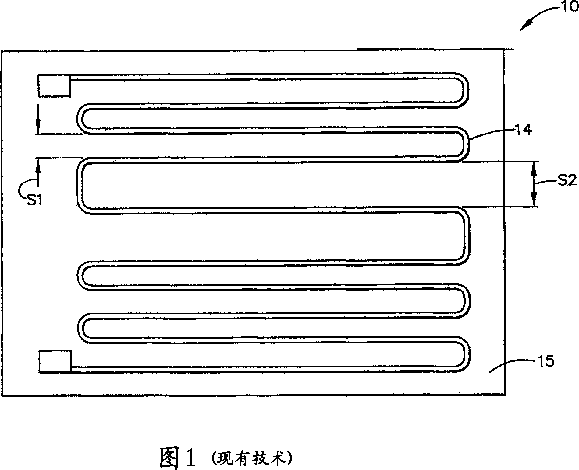
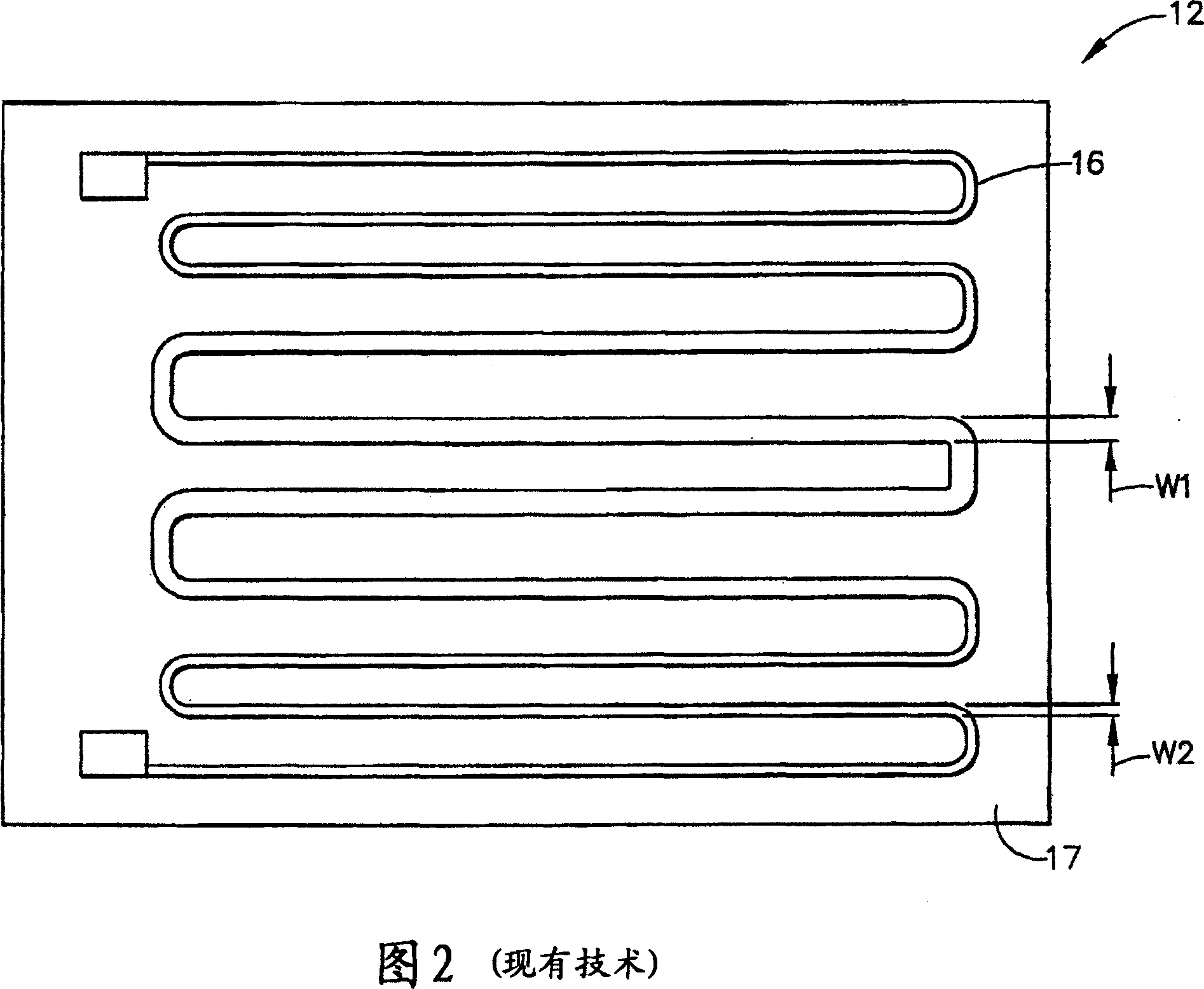
[0036] Referring to Figures 1 and 2, two (2) prior art heater systems 10 and 12 that provide variable watt density are shown. Prior art heater systems 10 and 12 each include resistive circuit patterns 14 and 16, respectively, which provide the required heat to the heated part or device. Generally, the resistive circuit pattern 14 in FIG. 1 is formed on a substrate 15 and includes a variable pitch (eg, S1 and S2) as shown to provide variable power density as desired. In the area of ​​S1, the spacing is closer and thus the power density is higher. Conversely, in the region of S2, the spacing is wider and thus the power density is lower.

[0037] As further shown in FIG. 2, resistive circuit pattern 16 is formed on a substrate 17 and includes a variable width (eg, W1 and W2) to provide variable power density as d...


PUM


Abstract

A layered heater is provided that includes at least one resistive layer having a resistive circuit pattern, the resistive circuit pattern defining a length, a width, and a thickness, wherein the thickness varies along the length of the resistive circuit pattern and/or the width of the resistive circuit pattern for a variable watt density. The present disclosure also provides layered heaters having a resistive circuit pattern with a variable thickness along with a variable width and/or spacing of the resistive circuit pattern in order to produce a variable watt density.

Description

technical field [0001] The present invention relates generally to electric heaters and, in particular, to apparatus and methods for distributing the power density of electric heaters. Background technique [0002] Layered heaters are typically used in applications where space is limited, thermal power needs to be varied across a surface, rapid thermal response is desired, or in ultra-clean applications where moisture or other contaminants may drift into conventional heaters. A layered heater generally comprises layers of different materials, namely a dielectric and a resistive material, which are applied to the substrate. A dielectric material is first applied to the substrate and provides electrical isolation between the substrate and the electrically-like resistive material, as well as reducing current leakage to ground during operation. The resistive material is applied to the dielectric material in a predetermined pattern and provides a resistive heater circuit. Layere...

Claims


Application Information

Patent Timeline
IPC IPC(8): H05B3/26H05B3/28H05K1/02H05K1/16H05K3/12
CPCH05K2201/09736H05B2203/037H05B2203/013H05K1/167H05B3/26H05K2203/0126H05K1/0263H05K3/1241H05K1/0265H05B3/20H05B2203/017H05B2203/003H05B3/28Y10T29/49099
Inventor 凯文·普塔西恩斯基詹姆斯·麦克米林托马斯·T·纳戈尔罗兰多·O·朱利安诺
Owner WATLOW ELECTRIC MFG
Why Eureka
Try Eureka